Page 3068 of 4323
SA23R±03
F14315
R12773
SA±64
± SUSPENSION AND AXLEFRONT SHOCK ABSORBER
3060 Author�: Date�:
2005 SEQUOIA (RM1146U)
REMOVAL
1. REMOVE FRONT WHEEL
2. DISCONNECT SHOCK ABSORBER FROM LOWER
SUSPENSION ARM
(a) Remove the shock absorber lower side set nut and wash-
er.
NOTICE:
Do not remove the bolt.
(b) Pry down the lower suspension arm to remove the bolt
and disconnect the shock absorber.
3. REMOVE SHOCK ABSORBER WITH COIL SPRING
Remove the 3 nuts and shock absorber with the coil spring.
Page 3069 of 4323
SA23S±03
F14523
± SUSPENSION AND AXLEFRONT SHOCK ABSORBER
SA±65
3061 Author�: Date�:
2005 SEQUOIA (RM1146U)
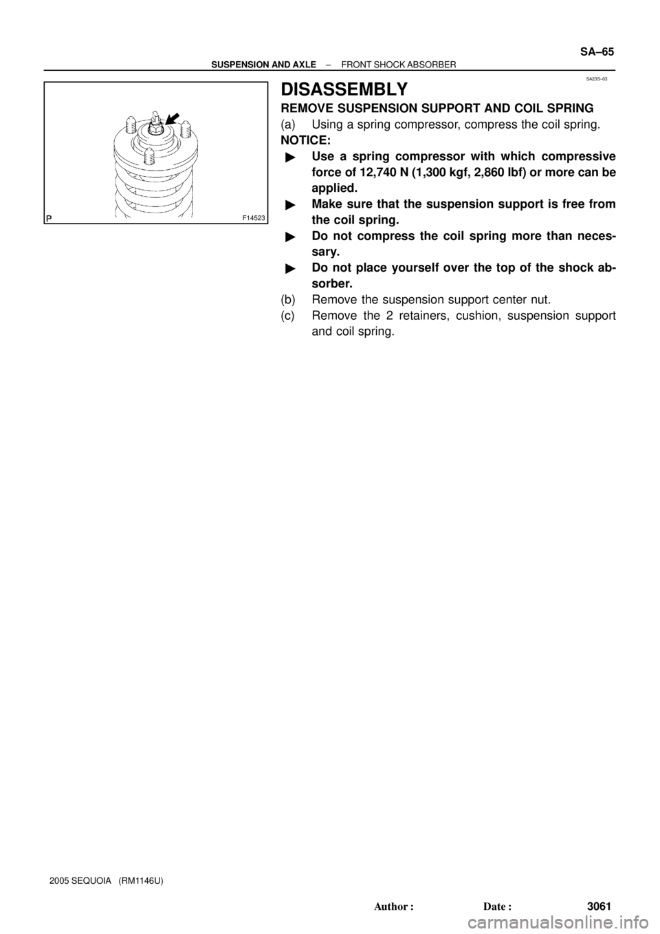
DISASSEMBLY
REMOVE SUSPENSION SUPPORT AND COIL SPRING
(a) Using a spring compressor, compress the coil spring.
NOTICE:
�Use a spring compressor with which compressive
force of 12,740 N (1,300 kgf, 2,860 lbf) or more can be
applied.
�Make sure that the suspension support is free from
the coil spring.
�Do not compress the coil spring more than neces-
sary.
�Do not place yourself over the top of the shock ab-
sorber.
(b) Remove the suspension support center nut.
(c) Remove the 2 retainers, cushion, suspension support
and coil spring.
Page 3072 of 4323
SA23T±03
F14318
SST
F14319
SST
SA±68
± SUSPENSION AND AXLEFRONT SHOCK ABSORBER
3064 Author�: Date�:
2005 SEQUOIA (RM1146U)
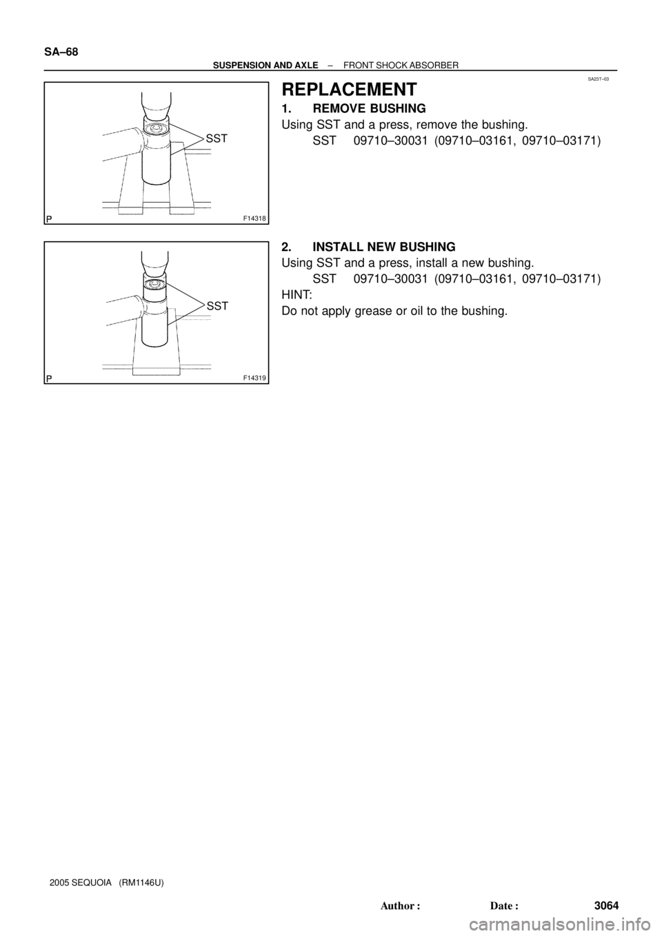
REPLACEMENT
1. REMOVE BUSHING
Using SST and a press, remove the bushing.
SST 09710±30031 (09710±03161, 09710±03171)
2. INSTALL NEW BUSHING
Using SST and a press, install a new bushing.
SST 09710±30031 (09710±03161, 09710±03171)
HINT:
Do not apply grease or oil to the bushing.
Page 3073 of 4323
SA23V±03
F14524
F07365
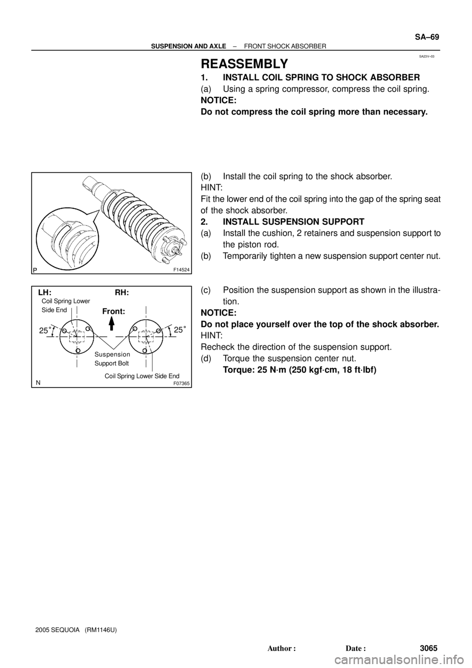
Suspension
Support Bolt
25°25° LH: RH:
Coil Spring Lower Side End
Coil Spring Lower
Side End
Front:
± SUSPENSION AND AXLEFRONT SHOCK ABSORBER
SA±69
3065 Author�: Date�:
2005 SEQUOIA (RM1146U)
REASSEMBLY
1. INSTALL COIL SPRING TO SHOCK ABSORBER
(a) Using a spring compressor, compress the coil spring.
NOTICE:
Do not compress the coil spring more than necessary.
(b) Install the coil spring to the shock absorber.
HINT:
Fit the lower end of the coil spring into the gap of the spring seat
of the shock absorber.
2. INSTALL SUSPENSION SUPPORT
(a) Install the cushion, 2 retainers and suspension support to
the piston rod.
(b) Temporarily tighten a new suspension support center nut.
(c) Position the suspension support as shown in the illustra-
tion.
NOTICE:
Do not place yourself over the top of the shock absorber.
HINT:
Recheck the direction of the suspension support.
(d) Torque the suspension center nut.
Torque: 25 N´m (250 kgf´cm, 18 ft´lbf)
Page 3074 of 4323
SA182±06
SA±70
± SUSPENSION AND AXLEFRONT SHOCK ABSORBER
3066 Author�: Date�:
2005 SEQUOIA (RM1146U)
INSTALLATION
1. INSTALL SHOCK ABSORBER WITH COIL SPRING
(a) Install the upper side of the shock absorber to the chassis frame with the 3 nuts.
Torque: 64 N´m (650 kgf´cm, 47 ft´lbf)
(b) Connect the lower side of the shock absorber to the lower suspension arm with the bolt, washer and
nut.
Torque: 135 N´m (1,400 kgf´cm, 100 ft´lbf)
2. INSTALL FRONT WHEEL
Torque: 110 N´m (1,150 kgf´cm, 83 ft´lbf)
Page 3075 of 4323
SA183±05
F07268
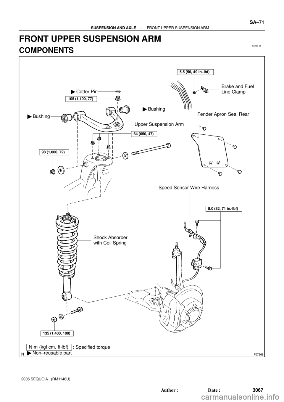
Upper Suspension Arm
N´m (kgf´cm, ft´lbf)
: Specified torque
� Non±reusable part
Brake and Fuel
Line Clamp
Fender Apron Seal Rear
Speed Sensor Wire Harness � Bushing
� Bushing � Cotter Pin
105 (1,100, 77)
64 (650, 47)
98 (1,000, 72)
135 (1,400, 100)
Shock Absorber
with Coil Spring
8.0 (82, 71 in.´lbf)
5.5 (56, 49 in.´lbf)
± SUSPENSION AND AXLEFRONT UPPER SUSPENSION ARM
SA±71
3067 Author�: Date�:
2005 SEQUOIA (RM1146U)
FRONT UPPER SUSPENSION ARM
COMPONENTS
Page 3076 of 4323
SA23W±03
R13196
SST
F07269
F07270
SA±72
± SUSPENSION AND AXLEFRONT UPPER SUSPENSION ARM
3068 Author�: Date�:
2005 SEQUOIA (RM1146U)
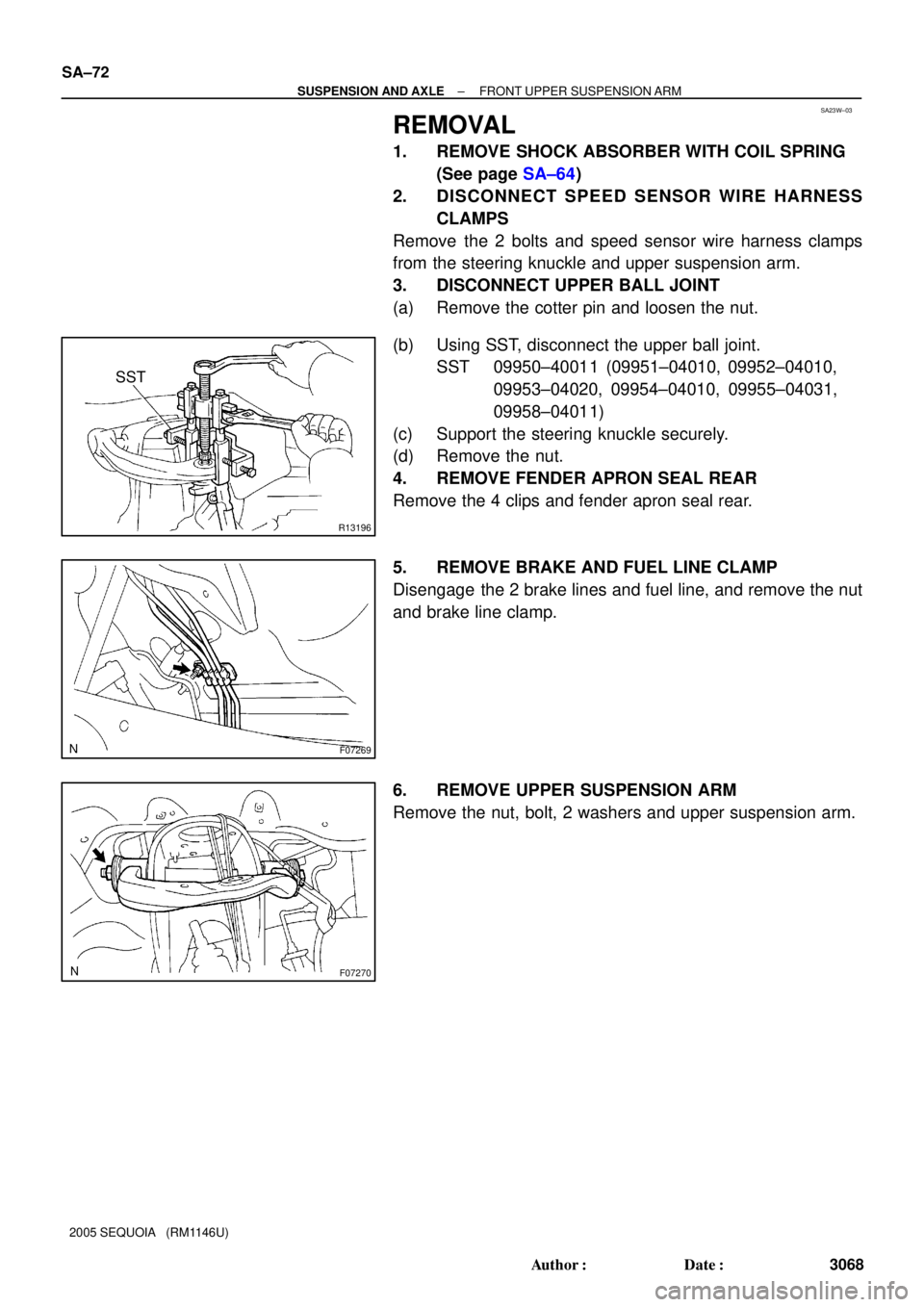
REMOVAL
1. REMOVE SHOCK ABSORBER WITH COIL SPRING
(See page SA±64)
2. DISCONNECT SPEED SENSOR WIRE HARNESS
CLAMPS
Remove the 2 bolts and speed sensor wire harness clamps
from the steering knuckle and upper suspension arm.
3. DISCONNECT UPPER BALL JOINT
(a) Remove the cotter pin and loosen the nut.
(b) Using SST, disconnect the upper ball joint.
SST 09950±40011 (09951±04010, 09952±04010,
09953±04020, 09954±04010, 09955±04031,
09958±04011)
(c) Support the steering knuckle securely.
(d) Remove the nut.
4. REMOVE FENDER APRON SEAL REAR
Remove the 4 clips and fender apron seal rear.
5. REMOVE BRAKE AND FUEL LINE CLAMP
Disengage the 2 brake lines and fuel line, and remove the nut
and brake line clamp.
6. REMOVE UPPER SUSPENSION ARM
Remove the nut, bolt, 2 washers and upper suspension arm.
Page 3078 of 4323

INSTALLATION
1. INSTALL UPPER SUSPENSION ARM
Install the upper suspension arm with the 2")
SA187±06
SA±74
± SUSPENSION AND AXLEFRONT UPPER SUSPENSION ARM
3070 Author�: Date�:
2005 SEQUOIA (RM1146U)
INSTALLATION
1. INSTALL UPPER SUSPENSION ARM
Install the upper suspension arm with the 2 washers, bolt and nut.
Torque: 98 N´m (1,000 kgf´cm, 72 ft´lbf)
HINT:
After stabilizing the suspension, torque the nut.
2. INSTALL BRAKE AND FUEL LINE CLAMP
Torque: 5.5 N´m (56 kgf´cm, 49 in.´lbf)
3. INSTALL FENDER APRON SEAL REAR
4. CONNECT UPPER BALL JOINT
(a) Connect the upper ball joint to the upper suspension arm.
(b) Install the nut and a new cotter pin.
If the holes for the cotter pin are not aligned, tighten the nut further up to 60°.
Torque: 105 N´m (1,100 kgf´cm, 77 ft´lbf)
5. CONNECT SPEED SENSOR WIRE HARNESS CLAMPS
Torque: 8.0 N´m (82 kgf´cm, 71 in.´lbf)
6. INSTALL SHOCK ABSORBER WITH COIL SPRING (See page SA±70)
7. CHECK FRONT WHEEL ALIGNMENT (See page SA±4)
8. PERFORM ZERO POINT CALIBRATION OF STEERING ANGLE, MASTER CYLINDER PRES-
SURE, YAW RATE AND DECELERATION SENSORS (See page DI±897)