Page 3030 of 4323

REASSEMBLY
1. INSTALL NEW BEARING
(a")
SA146±08
R13277
SST
SST
R13278
SST
SST
R13279
SST
R13215
SST
R13418
SST SA±26
± SUSPENSION AND AXLEFRONT AXLE HUB
3022 Author�: Date�:
2005 SEQUOIA (RM1146U)
REASSEMBLY
1. INSTALL NEW BEARING
(a) Using SST and a press, install a new bearing to the steer-
ing knuckle.
SST 09527±17011, 09950±60020 (09951±00910)
(b) Using snap ring pliers, install a new snap ring.
2. INSTALL NEW OIL SEAL (OUTSIDE)
(a) Using SST and a plastic hammer, install a new oil seal
(outside).
SST 09223±15030, 09527±17011
(b) Coat MP grease to the oil seal lip.
3. INSTALL AXLE HUB TO STEERING KNUCKLE
(a) Install the dust cover to the steering knuckle with the 4
bolts.
Torque: 18 N´m (185 kgf´cm, 13 ft´lbf)
(b) Using SST and a press, install the axle hub to the steering
knuckle.
SST 09649±17010
4. INSTALL SPEED SENSOR ROTOR
NOTICE:
Do not scratch the serration of the speed sensor rotor.
5. 2WD:
INSTALL NEW LOCK NUT
(a) Using SST, install and torque a new lock nut to the axle
hub.
SST 09318±12010
Torque: 274 N´m (2,800 kgf´cm, 203 ft´lbf)
(b) Using a chisel and hammer, stake the lock nut.
6. 4WD:
INSTALL BEARING SPACER
Using SST and a press, install the bearing spacer.
SST 09950±60010 (09951±00650),
09950±70010 (09951±07150)
7. 2WD:
INSTALL GREASE CAP
Page 3031 of 4323
R13280
SST
± SUSPENSION AND AXLEFRONT AXLE HUB
SA±27
3023 Author�: Date�:
2005 SEQUOIA (RM1146U)
8. 4WD:
INSTALL NEW OIL SEAL (INSIDE)
(a) Using SST and a plastic hammer, install a new oil seal (in-
side).
SST 09527±17011
HINT:
Lightly strike the SST on its circumference evenly.
(b) Coat MP grease to the oil seal lip.
Page 3032 of 4323

INSTALLATION
1. INSTALL STEERING KNUCKLE
(a) 4WD:
Insert the drive shaft into the axle hub and temp")
SA23J±05
SA±28
± SUSPENSION AND AXLEFRONT AXLE HUB
3024 Author�: Date�:
2005 SEQUOIA (RM1146U)
INSTALLATION
1. INSTALL STEERING KNUCKLE
(a) 4WD:
Insert the drive shaft into the axle hub and temporarily tighten the nut.
NOTICE:
Be careful not to damage the oil seal and drive shaft boot.
(b) Connect the steering knuckle to the upper suspension arm.
(c) Install the nut and a new cotter pin.
If the holes for the cotter pin are not aligned, tighten the nut further up to 60°.
Torque: 105 N´m (1,100 kgf´cm, 77 ft´lbf)
2. CONNECT LOWER BALL JOINT
Connect the lower ball joint to the steering knuckle with the 4 bolts.
Torque: 65 N´m (663 kgf´cm, 48 ft´lbf)
3. INSTALL SHOCK ABSORBER (See page SA±70)
4. INSTALL BRAKE CALIPER
(a) Install the disc, brake caliper and 2 bolts.
Torque: 123 N´m (1,250 kgf´cm, 90 ft´lbf)
(b) Install the brake line clamp to the steering knuckle with the bolt.
Torque: 28 N´m (285 kgf´cm, 21 ft´lbf)
5. CONNECT SPEED SENSOR AND WIRE HARNESS CLAMP
Connect the speed sensor and wire harness clamp to the steering knuckle with the 2 bolts.
Torque: 8.0 N´m (82 kgf´cm, 71 ft´lbf)
6. 4WD:
INSTALL DRIVE SHAFT LOCK NUT
(a) While applying the brakes, tighten the nut.
Torque: 235 N´m (2,400 kgf´cm, 173 ft´lbf)
(b) Install the lock cap and a new cotter pin.
If the holes for the cotter pin are not aligned, tighten the nut further up to 60°.
7. INSTALL GREASE CAP
8. INSTALL FRONT WHEEL
Torque: 110 N´m (1,150 kgf´cm, 83 ft´lbf)
9. DEPRESS BRAKE PEDAL SEVERAL TIMES
10. CHECK FRONT WHEEL ALIGNMENT (See page SA±4)
11. CHECK SPEED SENSOR SIGNAL (See page DI±899)
12. PERFORM ZERO POINT CALIBRATION OF STEERING ANGLE, MASTER CYLINDER PRES-
SURE, YAW RATE AND DECELERATION SENSORS (See page DI±897)
Page 3034 of 4323
SA14E±08
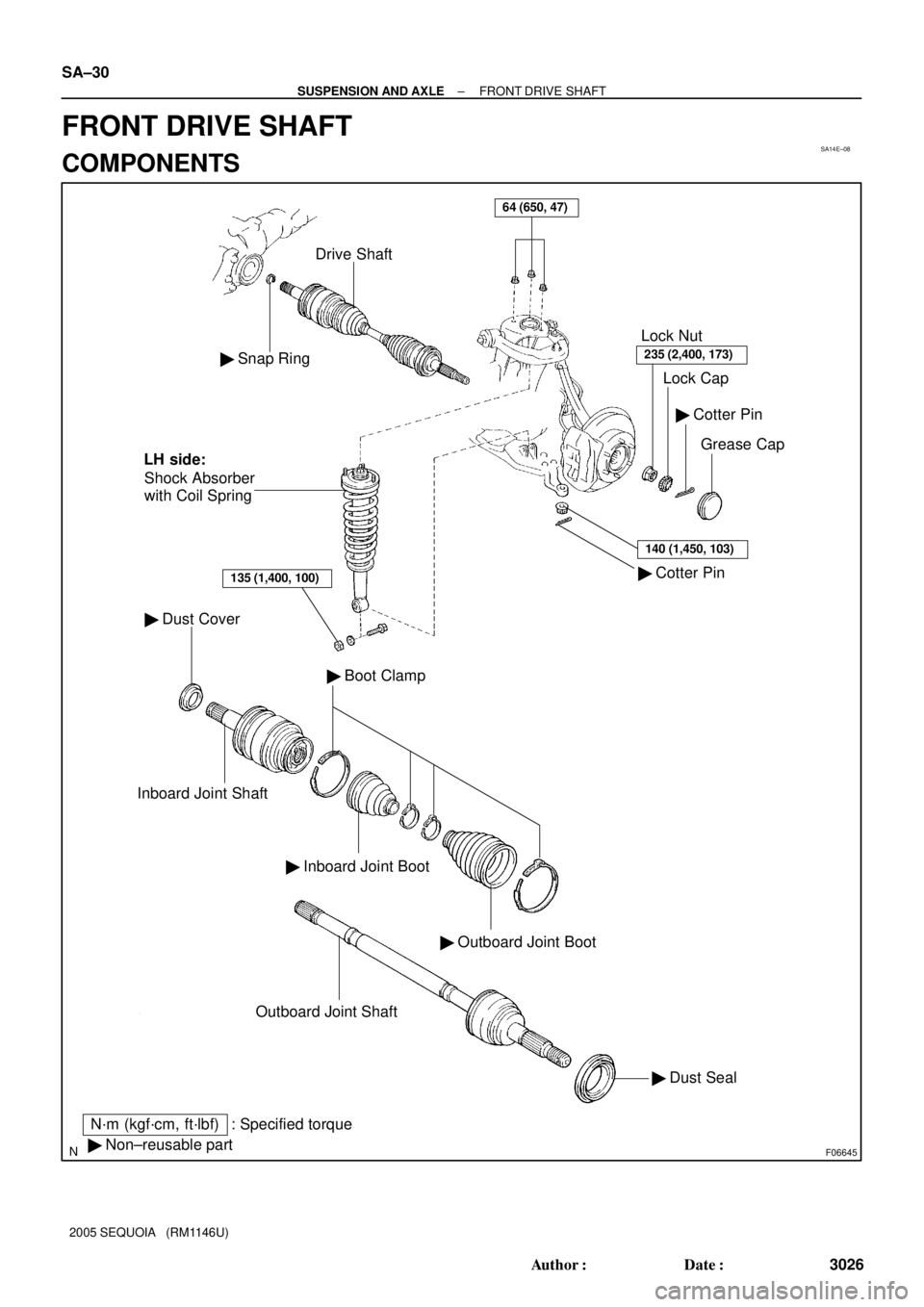
F06645
� Snap Ring
Drive Shaft
� Dust Cover
Inboard Joint Shaft
� Inboard Joint Boot
� Outboard Joint Boot
� Boot Clamp
� Dust Seal Outboard Joint Shaft
� Cotter Pin� Cotter Pin
Grease Cap Lock Cap Lock Nut
235 (2,400, 173)
140 (1,450, 103)
� Non±reusable part
N´m (kgf´cm, ft´lbf) : Specified torqueShock Absorber
with Coil Spring
135 (1,400, 100)
LH side:
64 (650, 47)
SA±30
± SUSPENSION AND AXLEFRONT DRIVE SHAFT
3026 Author�: Date�:
2005 SEQUOIA (RM1146U)
FRONT DRIVE SHAFT
COMPONENTS
Page 3035 of 4323
SA24L±03
F06624
R12863
SST
R13233
± SUSPENSION AND AXLEFRONT DRIVE SHAFT
SA±31
3027 Author�: Date�:
2005 SEQUOIA (RM1146U)
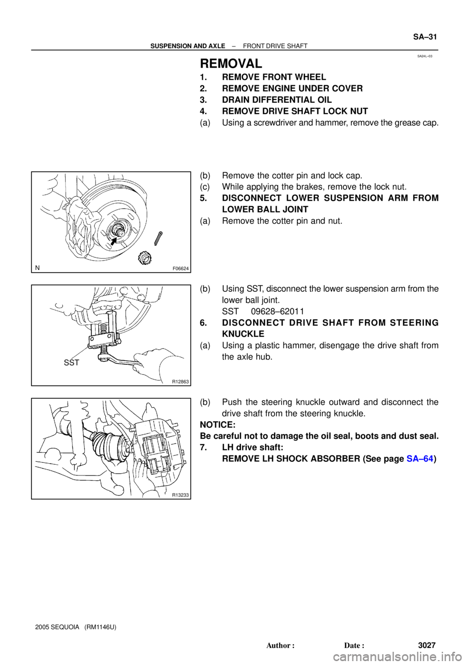
REMOVAL
1. REMOVE FRONT WHEEL
2. REMOVE ENGINE UNDER COVER
3. DRAIN DIFFERENTIAL OIL
4. REMOVE DRIVE SHAFT LOCK NUT
(a) Using a screwdriver and hammer, remove the grease cap.
(b) Remove the cotter pin and lock cap.
(c) While applying the brakes, remove the lock nut.
5. DISCONNECT LOWER SUSPENSION ARM FROM
LOWER BALL JOINT
(a) Remove the cotter pin and nut.
(b) Using SST, disconnect the lower suspension arm from the
lower ball joint.
SST 09628±62011
6. DISCONNECT DRIVE SHAFT FROM STEERING
KNUCKLE
(a) Using a plastic hammer, disengage the drive shaft from
the axle hub.
(b) Push the steering knuckle outward and disconnect the
drive shaft from the steering knuckle.
NOTICE:
Be careful not to damage the oil seal, boots and dust seal.
7. LH drive shaft:
REMOVE LH SHOCK ABSORBER (See page SA±64)
Page 3036 of 4323
F07267
SSTLH: RH:
SST
SA±32
± SUSPENSION AND AXLEFRONT DRIVE SHAFT
3028 Author�: Date�:
2005 SEQUOIA (RM1146U)
8. REMOVE DRIVE SHAFT
(a) RH drive shaft:
Using a brass bar and hammer, remove the RH drive
shaft.
NOTICE:
Be careful not to damage the dust cover and oil seal.
(b) LH drive shaft:
Using SST, remove the LH drive shaft.
SST 09520±01010, 09520±24010 (09520±32040)
NOTICE:
Be careful not to damage the dust cover and oil seal.
(c) Using a screwdriver, remove the snap ring from the in-
board joint shaft.
Page 3040 of 4323

INSTALLATION
1. INSTALL DRIVE SHAFT TO DIFFERENTIAL
(a) Install a new snap ring to the inboard jo")
SA14I±10
SA±36
± SUSPENSION AND AXLEFRONT DRIVE SHAFT
3032 Author�: Date�:
2005 SEQUOIA (RM1146U)
INSTALLATION
1. INSTALL DRIVE SHAFT TO DIFFERENTIAL
(a) Install a new snap ring to the inboard joint shaft.
(b) Apply gear oil to the inboard joint shaft and differential case sliding surface.
(c) Set the snap ring with opening side facing downward.
(d) Using a brass bar and hammer, install the drive shaft.
NOTICE:
Be careful not to damage the dust cover and oil seal.
HINT:
Whether the inboard joint shaft is in contact with the pinion shaft or not can be known from the sound or feel-
ing when driving.
(e) Check that there is 2 ± 3 mm (0.08 ± 0.12 in.) of play in the axial direction.
(f) Check that the drive shaft cannot be removed by hand.
2. LH drive shaft:
INSTALL LH SHOCK ABSORBER (See page SA±70)
3. CONNECT DRIVE SHAFT TO STEERING KNUCKLE
NOTICE:
Be careful not to damage the oil seal, boots and dust seal.
4. CONNECT LOWER SUSPENSION ARM TO LOWER BALL JOINT
(a) Connect the lower suspension arm to the lower ball joint.
(b) Install the nut and a new cotter pin.
If the holes for the cotter pin are not aligned, tighten the nut further up to 60°.
HINT:
Face the hole for the cotter pin forward.
Torque: 140 N´m (1,450 kgf´cm, 103 ft´lbf)
5. INSTALL DRIVE SHAFT LOCK NUT
(a) While applying brakes, install the nut.
Torque: 235 N´m (2,400 kgf´cm, 173 ft´lbf)
(b) Install the lock cap and a new cotter pin.
If the holes for the cotter pin are not aligned, tighten the nut further up to 60°.
6. FILL DIFFERENTIAL WITH HYPOID GEAR OIL (See page SA±38)
7. INSTALL ENGINE UNDER COVER
8. INSTALL FRONT WHEEL
Torque: 110 N´m (1,150 kgf´cm, 83 ft´lbf)
Page 3041 of 4323
SA23K±03
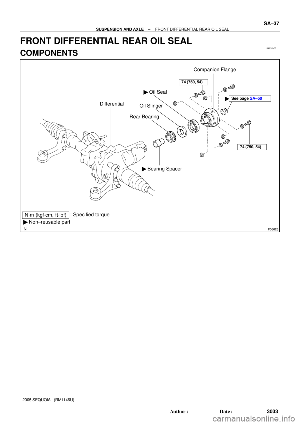
F06626
� Non±reusable part� Bearing Spacer
N´m (kgf´cm, ft´lbf): Specified torque
Differential
� Oil Seal
Oil Slinger
Rear Bearing
74 (750, 54)
Companion Flange
74 (750, 54)
�See page SA±50
± SUSPENSION AND AXLEFRONT DIFFERENTIAL REAR OIL SEAL
SA±37
3033 Author�: Date�:
2005 SEQUOIA (RM1146U)
FRONT DIFFERENTIAL REAR OIL SEAL
COMPONENTS