Page 2924 of 4323
D13866
AT±8
± AUTOMATIC TRANSMISSION (A750E, A750F)ATF TEMPERATURE SENSOR
2916 Author�: Date�:
2005 SEQUOIA (RM1146U)
7. INSTALL OIL PAN
HINT:
Remove any packing material, and be careful not to spill oil on
the contacting surfaces of the transmission case and the oil
pan.
Using a new gasket, install the oil pan with the 20 bolts.
Torque: 4.4 N´m (45 kgf´cm, 39 in´lbf)
8. FILL WITH ATF AND CHECK ATF LEVEL
(a) Remove the refill plug (See page DI±524).
(b) Fill with new fluid through the refill hole.
Fluid type: Toyota genuine ATF WS
Page 2926 of 4323
VALVE BODY ASSEMBLY
2918 Author�: Date�:
2005 SEQUOIA (RM1146U)
VALVE BOD")
D13867
AT136±01
D13866
AT0103
D12703
D12704
Orange
Blue
Clamp
ClampBolt
Bolt AT±10
± AUTOMATIC TRANSMISSION (A750E, A750F)VALVE BODY ASSEMBLY
2918 Author�: Date�:
2005 SEQUOIA (RM1146U)
VALVE BODY ASSEMBLY
ON±VEHICLE REPAIR
1. DRAIN AUTOMATIC TRANSMISSION FLUID
(a) Remove the drain plug and gasket, and drain the ATF.
(b) Install a new gasket and the drain plug.
Torque: 20 N´m (204 kgf´cm, 15 ft´lbf)
2. REMOVE OIL PAN
NOTICE:
Some fluid will remain in the oil pan.
(a) Remove the 20 bolts.
(b) Remove the oil pan gasket.
3. EXAMINE PARTICLES IN PAN
Remove the magnets and use them to collect any steel par-
ticles. Carefully look at the foreign matter and particles in the
pan and on the magnets to anticipate the type of wear you will
find in the transmission.
Steel (magnetic) ... bearing, gear and clutch plate wear
Brass (non±magnetic) ... bushing wear
4. REMOVE OIL STRAINER
Remove the 4 bolts, the oil strainer and the O±ring.
NOTICE:
Be careful as some fluid will come out with the oil strainer.
5. REMOVE ATF TEMPERATURE SENSOR
(a) Disconnect the 7 solenoid valve connectors.
(b) Remove the 2 bolts, clamps and ATF temperature sen-
sors.
Page 2928 of 4323
VALVE BODY ASSEMBLY
2920 Author�: Date�:
2005 SEQUOIA (RM1146U)
(b) Install the 19 bolts and th")
D12705
D12704
Orange
Blue
Clamp
Clamp
A B
D12703
D13866
AT±12
± AUTOMATIC TRANSMISSION (A750E, A750F)VALVE BODY ASSEMBLY
2920 Author�: Date�:
2005 SEQUOIA (RM1146U)
(b) Install the 19 bolts and the valve body.
Torque: 11 N´m (112 kgf´cm, 8 ft´lbf)
Bolt length:
Bolt A: 25 mm (0.98 in.)
Bolt B: 36 mm (1.42 in.)
10. INSTALL TEMPERATURE SENSOR
(a) Connect the 7 solenoid valve connectors.
(b) Install the 2 temperature sensors and clamps to the valve
body with the 2 bolts.
HINT:
In order to install the ATF temperature sensors properly, check
the wire harness color prior to installation.
Torque:
A: 11 N´m (112 kgf´cm, 8 ft´lbf)
B: 10 N´m (100 kgf´cm, 7 ft´lbf)
Bolt length:
Bolt A: 36 mm (1.42 in.)
Bolt B: 12 mm (0.47 in.)
Sensor wire harness:
Wire harnessColor
for linear controlOrange
for oil temp. warning lampBlue
11. INSTALL OIL STRAINER
(a) Install a new O±ring.
(b) Install the oil strainer with the 4 bolts.
Torque: 10 N´m (100 kgf´cm, 7 ft´lbf)
12. INSTALL OIL PAN
HINT:
Remove any packing material, and be careful not to spill oil on
the contacting surfaces of the transmission case and the oil
pan.
Using a new gasket, install the oil pan with the 20 bolts.
Torque: 4.4 N´m (45 kgf´cm, 39 in´lbf)
Page 2931 of 4323
AT138±01
D10672
N´m (kgf´cm, ft´lbf) : Specified torqueOil Cooler PipeOil Cooler Bracket
Clip
ClipOil Cooler
11 (110, 8)
5.0 (50, 48 in.´lbf)
Clip
Grommet
Grommet
Condenser Mounting
Insulator
11 (110, 8)
Hose
Grommet
Condenser Mounting
Insulator
± AUTOMATIC TRANSMISSION (A750E, A750F)AIR COOLED OIL COOLER
AT±15
2923 Author�: Date�:
2005 SEQUOIA (RM1146U)
AIR COOLED OIL COOLER
COMPONENTS
Page 2932 of 4323
AT139±01
D10673
D10674
D10675
D05209
AT±16
± AUTOMATIC TRANSMISSION (A750E, A750F)AIR COOLED OIL COOLER
2924 Author�: Date�:
2005 SEQUOIA (RM1146U)
REMOVAL
1. REMOVE PIPE
Loosen the 2 clips and disconnect the 2 hoses.
2. REMOVE OIL COOLER
(a) Remove the 3 bolts and oil cooler.
Torque: 11 N´m (110 kgf´cm, 8 ft´lbf)
(b) Remove the bolt, transmission oil cooler bracket and
grommet.
Torque: 4.9 N´m (50 kgf´cm, 43 in.´lbf)
(c) Remove the 2 grommets and condenser mounting insula-
tors.
3. REMOVE OIL COOLER TUBE
(a) Loosen the 2 clips and disconnect the 2 hoses.
(b) Remove the bolt and oil cooler tube with the 2 hoses.
Torque: 5.0 N´m (50 kgf´cm, 48 in.´lbf)
(c) Loosen the 2 clips and disconnect the 2 hoses.
Page 2933 of 4323
AT13A±01
± AUTOMATIC TRANSMISSION (A750E, A750F)AIR COOLED OIL COOLER
AT±17
2925 Author�: Date�:
2005 SEQUOIA (RM1146U)
INSTALLATION
Installation is in the reverse order of removal (See page AT±16).
HINT:
After installation, check fluid level (See page DI±524).
Page 2939 of 4323
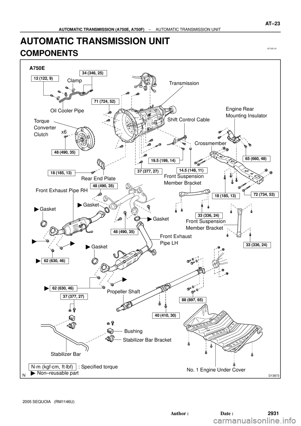
AT13E±01
D13873
A750E
Clamp
Oil Cooler Pipe34 (346, 25)
Torque
Converter
Clutchx6
Transmission
48 (490, 35)
71 (724, 52)
Front Exhaust Pipe RH
N´m (kgf´cm, ft´lbf) : Specified torque
�Non±reusable part
37 (377, 27)
Stabilizer BarBushing
Stabilizer Bar Bracket
No. 1 Engine Under Cover
40 (410, 30)
88 (897, 65)
18 (185, 13)
CrossmemberEngine Rear
Mounting Insulator
Shift Control Cable
37 (377, 27)
Gasket �
Front Exhaust
Pipe LH
Rear End Plate
18 (185, 13)
Gasket �
�62 (630, 46)
� �
62 (630, 46)
�
� Gasket
Propeller Shaft
19.5 (199, 14)
14.5 (148, 11)
65 (660, 48)
72 (734, 53)
33 (336, 24)
33 (336, 24)
�
� Gasket
48 (490, 35)
Front Suspension
Member Bracket Front Suspension
Member Bracket
12 (122, 9)
48 (490, 35)
± AUTOMATIC TRANSMISSION (A750E, A750F)AUTOMATIC TRANSMISSION UNIT
AT±23
2931 Author�: Date�:
2005 SEQUOIA (RM1146U)
AUTOMATIC TRANSMISSION UNIT
COMPONENTS
Page 2940 of 4323
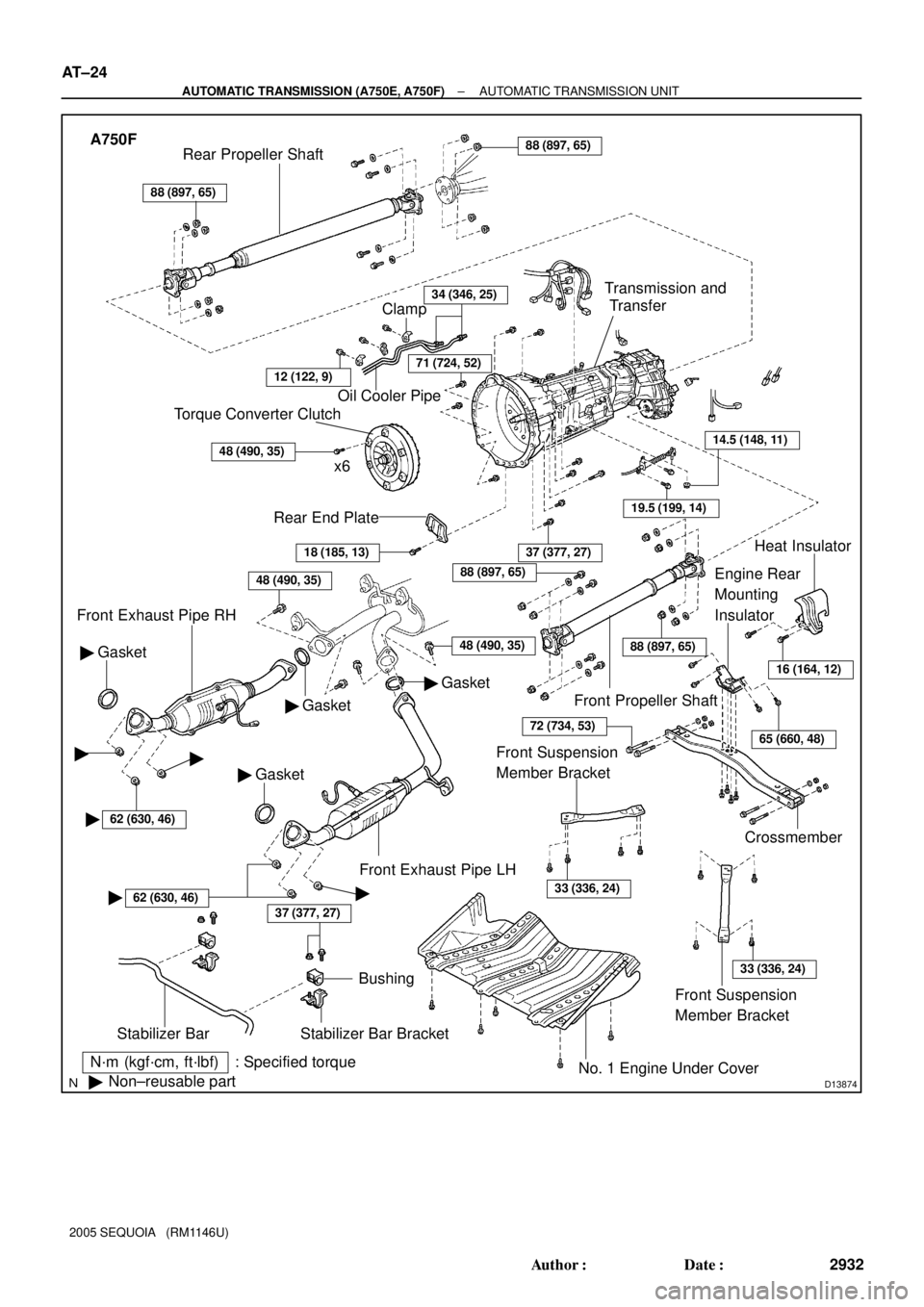
D13874
A750F
N´m (kgf´cm, ft´lbf) : Specified torque
�Non±reusable part
37 (377, 27)
Stabilizer Bar
Bushing
Stabilizer Bar Bracket
No. 1 Engine Under Cover
18 (185, 13)
Rear End Plate
Torque Converter Clutch
x6
48 (490, 35)
Oil Cooler Pipe
34 (346, 25)
Gasket �
Front Exhaust Pipe RH
Gasket �
� Gasket
37 (377, 27)
Crossmember
Engine Rear
Mounting
Insulator
19.5 (199, 14)
14.5 (148, 11)
Transmission and
Transfer
88 (897, 65)
Rear Propeller Shaft88 (897, 65)
Front Propeller Shaft
Heat Insulator
Front Exhaust Pipe LH
Clamp
71 (724, 52)
� Gasket
48 (490, 35)
16 (164, 12)
65 (660, 48)
88 (897, 65)
88 (897, 65)
72 (734, 53)
Front Suspension
Member Bracket
33 (336, 24)
Front Suspension
Member Bracket
33 (336, 24)
��
�62 (630, 46)
�62 (630, 46)�
12 (122, 9)
48 (490, 35)
AT±24
± AUTOMATIC TRANSMISSION (A750E, A750F)AUTOMATIC TRANSMISSION UNIT
2932 Author�: Date�:
2005 SEQUOIA (RM1146U)

 : Specified torqueOil Cooler PipeOil Cooler Bracket
Clip
ClipOil Cooler
11 (110, 8)
5.0 (50, 48 in.´lbf)
Clip
Grommet
Grommet
Condenser Mounting
Insulator
11")