Page 2980 of 4323
TR0DK±01
F19268
F19269
F19270
F19298
TR±34
± TRANSFERINPUT SHAFT
2972 Author�: Date�:
2005 SEQUOIA (RM1146U)
INSPECTION
1. REMOVE 2 OIL SEAL RINGS
2. INSPECT INPUT SHAFT
(a) Using a micrometer, measure the outer diameter of the in-
put shaft journal surface.
Minimum diameter: 47.59 mm (1.8736 in.)
If the outer diameter is less than the minimum, replace the input
shaft.
(b) Using a dial indicator, measure the inside diameter of the
input shaft bushing.
Maximum diameter: 48.14 mm (1.8953 in.)
If the inside diameter exceeds the maximum, replace the input
shaft.
3. INSTALL 2 OIL SEAL RINGS
HINT:
�Apply gear oil to the oil seal ring.
�Engage securely to eliminate clearance as shown in the
illustration.
Page 2994 of 4323
PR01H±04
F19347Matchmarks
R04164
SST
± PROPELLER SHAFTPROPELLER SHAFT ASSEMBLY (2WD)
PR±3
2986 Author�: Date�:
2005 SEQUOIA (RM1146U)
REMOVAL
REMOVE PROPELLER SHAFT
(a) Place matchmarks on the differential and propeller shaft
flanges.
(b) Remove the 4 nuts and washers.
(c) Pull out the propeller shaft yoke from the transmission.
(d) Insert SST in the transmission to prevent oil leakage.
SST 09325±40010
Page 3005 of 4323

TROUBLESHOOTING
PROBLEM SYMPTOMS TABLE
Use the table below to help you find the cause of the problem")
SA140±10
± SUSPENSION AND AXLETROUBLESHOOTING
SA±1
2997 Author�: Date�:
2005 SEQUOIA (RM1146U)
TROUBLESHOOTING
PROBLEM SYMPTOMS TABLE
Use the table below to help you find the cause of the problem. The numbers indicate the priority of the likely
cause of the problem. Check each part in order. If necessary, replace these parts.
SymptomSuspect AreaSee page
Bottoming
1. Vehicle (Overloaded)
2. Spring (Weak)
3. Shock absorber (Worn)±
SA±63
SA±135
SA±66
SA±135
Sways/pitches
1. Tire (Worn or improperly inflated)
2. Stabilizer bar (Bent or broken)
3. Shock absorber (Worn)SA±3
SA±90
SA±149
SA±66
SA±135
Front wheel shimmy
1. Tire (Worn or improperly inflated)
2. Wheel (Out of balance)
3. Shock absorber (Worn)
4. Wheel alignment (Incorrect)
5. Ball joints (Worn)
6. Hub bearing (Loose or worn)
7. Steering linkage (Loose or worn)
8. Steering gear (Out of adjustment or broken)SA±3
SA±3
SA±66
SA±4
SA±83
SA±88
SA±21
±
SR±37
Abnormal tire wear
1. Tire (Improperly inflated)
2. Wheel alignment (Incorrect)
3. Shock absorber (Worn)
4. Suspension parts (Worn)SA±3
SA±4
SA±66
SA±139
±
Noise in front differential
1. Oil level (Low or wrong grade)
2. Excessive backlash between pinion and ring gear
3. Ring, pinion or side gear (Worn or chipped)
4. Pinion shaft bearing (Worn)
5. Side bearing (Worn)
6. Differential bearing (Loose or worn)SA±38
SA±50
SA±50
SA±50
SA±50
SA±50
Oil leak from front differential
1. Oil level (Too high or wrong grade)
2. Front differential rear oil seal (Worn or damaged)
3. Side gear oil seal (Worn or damaged)
4. Companion flange (Loose or damaged)
5. Side gear shaft (Damaged)SA±38
SA±38
SA±50
SA±50
SA±50
Noise in rear axle
1. Oil level (Low or wrong grade)
2. Excessive backlash between pinion and ring gear
3. Ring, pinion or side gear (Worn or chipped)
4. Pinion shaft bearing (Worn)
5. Axle shaft bearing (Worn)
6. Differential bearing (Loose or worn)SA±105
SA±109
SA±109
SA±109
SA±94
SA±109
Oil leak from rear axle1. Oil seal (Worn or damaged)
2. Rear axle housing (Cracked)SA±94
±
Oil leak from rear differential
1. Oil level (Too high or wrong grade)
2. Oil seal (Worn or damaged)
3. Companion flange (Loose or damaged)SA±105
SA±105
SA±109
Page 3007 of 4323
(B)
R07928
± SUSPENSION AND AXLETIRE AND WHEEL
SA±3
2999 Author�: Date�:
2005 SEQUOIA (RM1146U)
TIRE AND WHEEL
INSPECTION
1. INSPECT TIRE
(a) Check the tires for")
SA17H±11
R03031
F13676
Front (A)(B)
R07928
± SUSPENSION AND AXLETIRE AND WHEEL
SA±3
2999 Author�: Date�:
2005 SEQUOIA (RM1146U)
TIRE AND WHEEL
INSPECTION
1. INSPECT TIRE
(a) Check the tires for wear and proper inflation pressure.
Cold tire inflation pressure:
Tire sizeFront
kPa (kgf/cm2, psi)
Rear
kPa (kgf/cm2, psi)
P245/70R16220 (2.2, 32)240 (2.4, 35)
P265/70R16220 (2.2, 32)220 (2.2, 32)
P265/65R17220 (2.2, 32)220 (2.2, 32)
(b) Using a dial indicator, check the tire runout.
Tire runout: 3.0 mm (0.118 in.) or less
2. ROTATING TIRE
HINT:
�Rotate tires as shown in the illustration.
�Rotate as shown in (B) if the spare tire is included in the
rotation.
3. INSPECT WHEEL BALANCE
(a) Check and adjust the Off±the±car balance.
(b) If necessary, check and adjust the On±the±car balance.
Imbalance after adjustment: 14.0 g (0.031 lb) or less
4. CHECK FRONT SUSPENSION FOR LOOSENESS
5. CHECK STEERING LINKAGE FOR LOOSENESS
6. CHECK BALL JOINT FOR LOOSENESS
7. CHECK SHOCK ABSORBER WORKS PROPERLY
�Check if oil leaks.
�Check the mounting bushings for wear.
�Bounce front and rear of the vehicle.
Page 3021 of 4323

F19826
Rim
Sensor
Cap
Nut
WasherGrommet
F19827
Area for the sensorRim
Rim rotating
direction
Rim rotating
directionRim
Area for the sensor
Mount tool of the mounting machine
Mount tool of the mounting machine
± SUSPENSION AND AXLETIRE PRESSURE MONITOR VALVE
SA±17
3013 Author�: Date�:
2005 SEQUOIA (RM1146U)
�If installed in the reverse direction, the tire pressure
monitor valve may be damaged or fail to transmit sig-
nals when running at high speed.
�If installing a new tire pressure monitor valve, write
down the ID number before installation.
�It is necessary to registor an ID in the ECU after instal-
lation (See page DI±805).
(b) Install the washer on the tire pressure monitor valve from
the rim side and tighten with a nut.
Torque: 4.0 NVm (41 kgfVcm, 35 in.Vlbf)
NOTICE:
�Check that there is no foreign matter on the washer
and nut.
�If the tire pressure monitor valve is removed when the
tire is removed for replacement, check that there is no
damage or cuts, and no foreign matter such as mud,
dirt or sand attached to the grommet. Replace the
grommet with a new one if any of the defects men-
tioned above are found.
�Check that there is no oil, water or lubricant around
the rim hole, tire pressure monitor valve, washer and
nut. Failing to do so may result in improper installa-
tion.
(c) After the tire is inflated, the valve nut may be loose. Re-
tighten the nut to the specified torque and then check for
air leaks with soapy water.
Torque: 4.0 NVm (41 kgfVcm, 35 in.Vlbf)
(d) Set the wheel disc to the mounting machine and install the
lower tire bead. Position the main body of the sensor as
in the shaded area shown in the illustration.
NOTICE:
If the sensor is positioned outside this area, it generates in-
terference with the tire bead, causing possible damage to
the sensor.
(e) Install the upper bead.
NOTICE:
Make sure that the tire bead and tool do not interfere with
the main body of the sensor and that the sensor is not
clamped by the bead.
5. INSTALL FRONT WHEEL
Torque: 103 NVm (1,050 kgfVcm, 76 ftVlbf)
6. INSTALL REAR WHEEL
Torque: 103 NVm (1,050 kgfVcm, 76 ftVlbf)
7. INSPECT TIRE (See page SA±3)
8. REGISTRATION OF TRANSMITTED ID
(See page DI±805)
Page 3025 of 4323
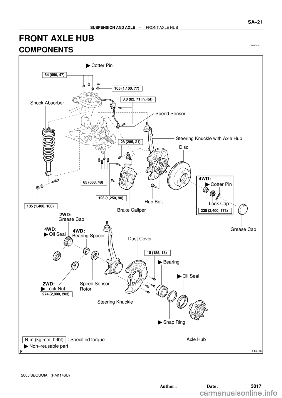
SA143±10
F14316
N´m (kgf´cm, ft´lbf) : Specified torque
� Non±reusable part
64 (650, 47)
Brake CaliperHub Bolt � Cotter Pin
105 (1,100, 77)
8.0 (82, 71 in.´lbf)
Speed Sensor
Shock Absorber
135 (1,400, 100)
65 (663, 48)
123 (1,250, 90)
28 (285, 21)Steering Knuckle with Axle Hub
Disc
4WD:
� Cotter Pin
235 (2,400, 173)
Lock Cap
Grease Cap
Grease Cap2WD:
4WD:
� Oil Seal
Speed Sensor
Rotor
Dust Cover
Steering Knuckle
18 (185, 13)
� Oil Seal � Bearing
� Snap Ring
Axle Hub
Bearing Spacer4WD:
274 (2,800, 203)
� Lock Nut 2WD:
± SUSPENSION AND AXLEFRONT AXLE HUB
SA±21
3017 Author�: Date�:
2005 SEQUOIA (RM1146U)
FRONT AXLE HUB
COMPONENTS
Page 3027 of 4323
R13196
SST
± SUSPENSION AND AXLEFRONT AXLE HUB
SA±23
3019 Author�: Date�:
2005 SEQUOIA (RM1146U)
(b) Using SST, disconnect the steering knuckle.
SST 09950±40011 (09951±04010, 09952±04010,
09553±04020, 09554±04010, 09955±04031,
09958±04011)
(c) Remove the nut and steering knuckle.
NOTICE:
4WD:
Be careful not to damage the oil seal and drive shaft boot.
HINT:
4WD:
When it is difficult to disconnect the drive shaft, tap the tip of the
drive shaft with a plastic hammer.
Page 3028 of 4323

DISASSEMBLY
1. 2WD:
REMOVE GREASE CAP
(a) Mount the axle hub in a soft ja")
SA145±08
R13215
SST
R13275
SST
SST SA±24
± SUSPENSION AND AXLEFRONT AXLE HUB
3020 Author�: Date�:
2005 SEQUOIA (RM1146U)
DISASSEMBLY
1. 2WD:
REMOVE GREASE CAP
(a) Mount the axle hub in a soft jaw vise.
HINT:
Close the vise until it holds hub bolts. Do not tighten further.
(b) Using a screwdriver, remove the grease cap.
2. 4WD:
REMOVE OIL SEAL (INSIDE)
(a) Mount the axle hub in a soft jaw vise.
HINT:
Close the vise until it holds hub bolts. Do not tighten further.
(b) Using a screwdriver, remove the oil seal (inside).
3. 2WD:
REMOVE LOCK NUT AND SPEED SENSOR ROTOR
(a) Using a chisel and hammer, loosen the staked part of the
lock nut.
NOTICE:
Be careful not to damage the bushing.
(b) Using SST, remove the lock nut.
SST 09318±12010
(c) Remove the speed sensor rotor.
NOTICE:
Take care not to scratch the serration of the speed sensor
rotor.
4. REMOVE AXLE HUB FROM STEERING KNUCKLE
(a) Remove the 4 bolts and shift the dust cover towards the
hub side (outside).
(b) Using SST, remove the axle hub from the steering
knuckle.
SST 09710±30021 (09710±03051),
09950±40011 (09951±04020, 09952±04010,
09953±04020, 09954±04010, 09955±04031,
09957±04010, 09958±04011)
(c) Remove the dust cover from the steering knuckle.
(d) 4WD:
Remove the bearing spacer and speed sensor rotor.
NOTICE:
Take care not to scratch the serration of the speed sensor
rotor.
5. REMOVE OIL SEAL (OUTSIDE)
Using a screwdriver, remove the oil seal (outside) from the
steering knuckle.
6. REMOVE BEARING FROM STEERING KNUCKLE
(a) Using snap ring pliers, remove the snap ring.