Page 2892 of 4323

P21088
Ohmmeter
No Continuity
P10821
Free
Lock
B12319
Terminal CTerminal 50
ContinuityOhmmeter
B12320ContinuityOhmmeter
Terminal 50
ST±10
± STARTINGSTARTER
2884 Author�: Date�:
2005 SEQUOIA (RM1146U)
12. INSPECT BRUSH HOLDER INSULATION
Using an ohmmeter, check that there is no continuity between
the positive (+) and negative (±) brush holders.
If there is continuity, repair or replace the brush holder.
13. INSPECT GEAR TEETH
Check the gear teeth on the pinion gear, idle gear and the clutch
assembly for wear or damage.
If any damage is found, replace the gear or clutch assembly,
and also check the drive plate ring gear for wear or damage.
14. INSPECT CLUTCH PINION GEAR
Rotate the pinion gear clockwise, and check that it turns freely.
Check that it locks by rotating the pinion gear counterclockwise.
If necessary, replace the clutch assembly.
15. INSPECT FRONT AND REAR BEARING
Turn the bearing by hand as applying inward force.
If resistance is felt or the bearing sticks, replace the bearing.
16. DO PULL±IN COIL OPEN CIRCUIT TEST
Using an ohmmeter, check that there is continuity between ter-
minals 50 and C.
If there is no continuity, replace the magnetic switch.
17. DO HOLDING COIL OPEN CIRCUIT TEST
Using an ohmmeter, check that there is continuity between ter-
minal 50 and the switch body.
If there is no continuity, replace the magnetic switch.
Page 2895 of 4323

(psi)
(kPa) = (psi) x 6.9100 kgf
2 Ram diameter (cm)
(kPa) = (kgf/cm
2) x 98.1 ==
x 3.14 (p)
2
221lbf
2 Ram diameter (in.)
x 3.14 (p)
2
B13044
SST
B1232")
B12323
33 mm20 mm
Contact
Plate
40 mm
(kgf/cm2)
(psi)
(kPa) = (psi) x 6.9100 kgf
2 Ram diameter (cm)
(kPa) = (kgf/cm
2) x 98.1 ==
x 3.14 (p)
2
221lbf
2 Ram diameter (in.)
x 3.14 (p)
2
B13044
SST
B12326
± STARTINGSTARTER
ST±13
2887 Author�: Date�:
2005 SEQUOIA (RM1146U)
(g) Tighten terminal nuts.
(1) Put a wooden block on the contact plate and press
it down with a hand press.
Dimensions of wooden block:
20 x 33 x 40 mm (0.79 x 1.30 x 1.57 in.)
Press force:
981 N (100 kgf, 221 lbf)
NOTICE:
�Check the diameter of the hand press ram. Then cal-
culate the gauge pressure of the press when
981 N (100 kgf, 221 lbf) of force is applied.
Gauge pressure:
�If the contact plate is not pressed down with the spe-
cified pressure, the contact plate may tilt due to coil
deformation or the tightening of the nut.
(2) Using SST, tighten the nuts to the specified torque.
SST 09810±38140
Torque: 17 N´m (170 kgf´cm, 13 ft´lbf)
NOTICE:
If the nut is over tightened, it may cause cracks on the plas-
tic frame.
(h) Clean contact surfaces of the contact plate and the plung-
er.
Clean the contact surfaces of the remaining contact plate
and plunger with a dry shop rag.
(i) Reinstall the magnetic switch end cover.
Install the plunger, the new gasket and the end cover with
the 3 nuts.
Torque: 3.6 N´m (37 kgf´cm, 32 in.´lbf)
Page 2897 of 4323

ST094±06
B02289
Terminal 50
Battery Terminal C
B02290
Battery Terminal CDisconnect
B02291
Disconnect
Battery
B02292
Terminal 30
Battery Ammeter Terminal 50
± STARTINGSTARTER
ST±15
2889 Author�: Date�:
2005 SEQUOIA (RM1146U)
TEST
NOTICE:
These tests must be done within 3 to 5 seconds to avoid the
coil to be burned ± out.
1. DO PULL±IN TEST
(a) Disconnect the field coil lead wire from terminal C.
(b) Connect the battery to the magnetic switch as shown.
Check that the pinion gear moves outward.
2. DO HOLDING TEST
While connected as above with the pinion gear out, disconnect
the negative (±) lead from terminal C. Check that the pinion gear
remains out.
3. INSPECT CLUTCH PINION GEAR RETURN
Disconnect the negative (±) lead from the starter body. Check
that the pinion gear returns inward.
4. DO NO±LOAD PERFORMANCE TEST
(a) Connect the battery and ammeter to the starter as shown.
(b) Check that the starter rotates smoothly and steadily with
the pinion gear moving out. Check that the ammeter
shows the specified current.
Specified current:
At 11.5 V: 100 A or less
Page 2909 of 4323
B16364
B16366
SST
± CHARGINGGENERATOR
CH±9
2901 Author�: Date�:
2005 SEQUOIA (RM1146U)
4. REMOVE COIL ASSEMBLY
(a) Remove the 4 bolts.
(b) Using SST, remove the coil assembly.
SST 09950±40011 (09951±04020, 09952±04010
09953±04020, 09954±04010, 09955±04071,
09958±04011)
(c) Remove the generator washer.
5. REMOVE ROTOR FROM DRIVE END FRAME
Page 2913 of 4323
CH0M2±02
B16368
Pulley
B16367
B12276
SST
B16364
B16369
TurnSST (A)
SST (B)
± CHARGINGGENERATOR
CH±13
2905 Author�: Date�:
2005 SEQUOIA (RM1146U)
REASSEMBLY
1. INSTALL ROTOR TO DRIVE END FRAME
(a) Place the drive end frame on the pulley.
(b) Install the rotor to the drive end frame.
2. INSTALL COIL ASSEMBLY
(a) Place the generator washer on the rotor.
(b) Using SST and a press, slowly press in the coil assembly.
SST 09285±76010
(c) Install the coil assembly with the 4 bolts.
Torque: 5.8 N´m (59 kgf´cm, 51 in.´lbf)
3. INSTALL PULLEY
(a) Install the pulley to the rotor shaft by tightening the pulley
nut by hand.
(b) Hold SST (A) with a torque wrench, and tighten SST (B)
clockwise to the specified torque.
SST 09820±63011
Torque: 39 N´m (400 kgf´cm, 29 ft´lbf)
(c) Check that SST (A) is secured to the pulley shaft.
Page 2914 of 4323
B16371
SST (C)
SST (A)
Insert
B16373
SST (C)
SST (A)
Turn
B16370SST (B)
SST (A) Turn
B16361
Upward
Pin
B16359
CH±14
± CHARGINGGENERATOR
2906 Author�: Date�:
2005 SEQUOIA (RM1146U)
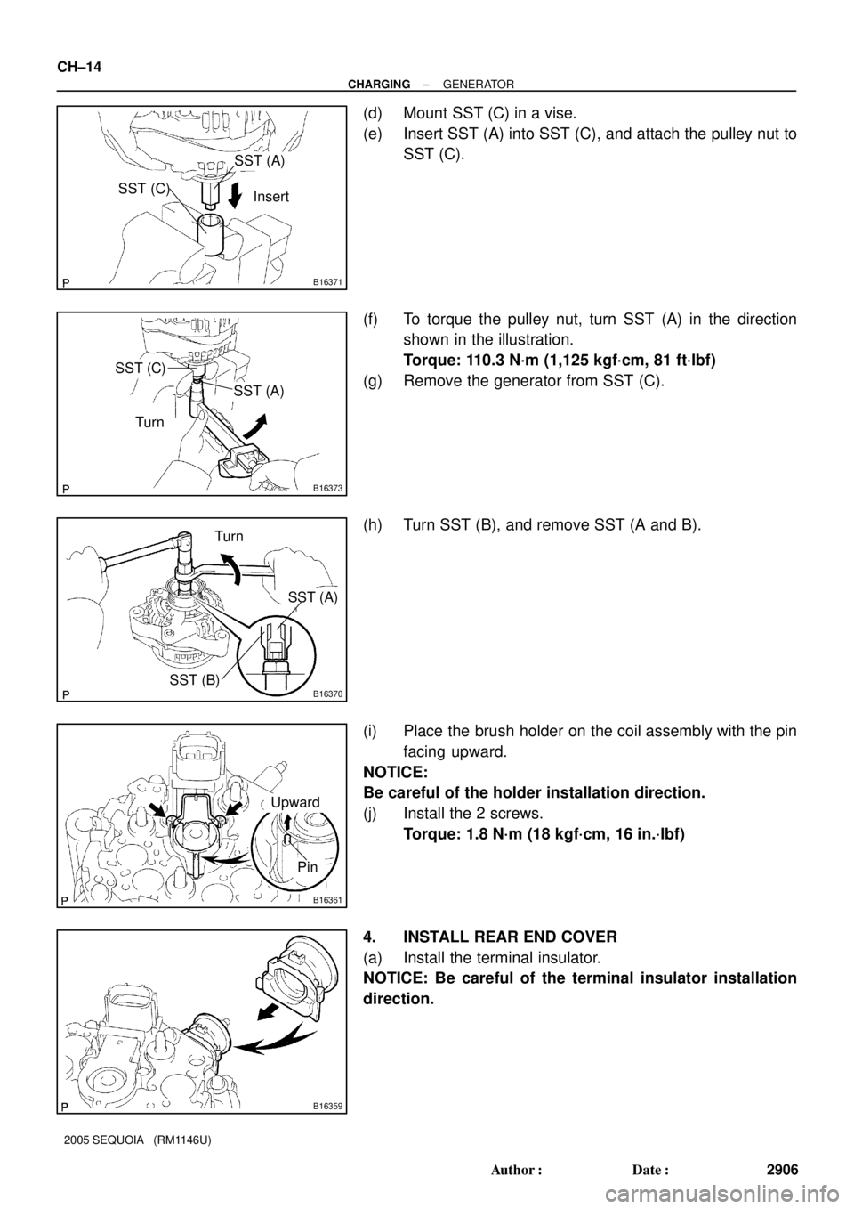
(d) Mount SST (C) in a vise.
(e) Insert SST (A) into SST (C), and attach the pulley nut to
SST (C).
(f) To torque the pulley nut, turn SST (A) in the direction
shown in the illustration.
Torque: 110.3 N´m (1,125 kgf´cm, 81 ft´lbf)
(g) Remove the generator from SST (C).
(h) Turn SST (B), and remove SST (A and B).
(i) Place the brush holder on the coil assembly with the pin
facing upward.
NOTICE:
Be careful of the holder installation direction.
(j) Install the 2 screws.
Torque: 1.8 N´m (18 kgf´cm, 16 in.´lbf)
4. INSTALL REAR END COVER
(a) Install the terminal insulator.
NOTICE: Be careful of the terminal insulator installation
direction.
Page 2920 of 4323
D13867
AT132±01
OR0004
SST
OR0005
SST
AT±4
± AUTOMATIC TRANSMISSION (A750E, A750F)EXTENSION HOUSING OIL SEAL (A750E)
2912 Author�: Date�:
2005 SEQUOIA (RM1146U)
EXTENSION HOUSING OIL SEAL
(A750E)
ON±VEHICLE REPAIR
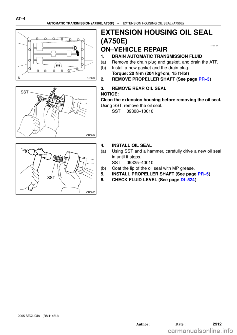
1. DRAIN AUTOMATIC TRANSMISSION FLUID
(a) Remove the drain plug and gasket, and drain the ATF.
(b) Install a new gasket and the drain plug.
Torque: 20 N´m (204 kgf´cm, 15 ft´lbf)
2. REMOVE PROPELLER SHAFT (See page PR±3)
3. REMOVE REAR OIL SEAL
NOTICE:
Clean the extension housing before removing the oil seal.
Using SST, remove the oil seal.
SST 09308±10010
4. INSTALL OIL SEAL
(a) Using SST and a hammer, carefully drive a new oil seal
in until it stops.
SST 09325±40010
(b) Coat the lip of the oil seal with MP grease.
5. INSTALL PROPELLER SHAFT (See page PR±5)
6. CHECK FLUID LEVEL (See page DI±524)
Page 2923 of 4323
ATF TEMPERATURE SENSOR
AT±7
2915 Author�: Date�:
2005 SEQUOI")
D13867
AT134±01
D12704
Orange
Blue
Clamp
ClampBolt
Bolt
D12739
D12704
Orange
Blue
Clamp
Clamp
A B
± AUTOMATIC TRANSMISSION (A750E, A750F)ATF TEMPERATURE SENSOR
AT±7
2915 Author�: Date�:
2005 SEQUOIA (RM1146U)
ATF TEMPERATURE SENSOR
ON±VEHICLE REPAIR
1. DRAIN AUTOMATIC TRANSMISSION FLUID
(a) Remove the drain plug and gasket, and drain the ATF.
(b) Install a new gasket and the drain plug.
Torque: 20 N´m (204 kgf´cm, 15 ft´lbf)
2. REMOVE OIL PAN (See page AT±10)
3. REMOVE OIL STRAINER (See page AT±10)
4. REMOVE ATF TEMPERATURE SENSOR
(a) Disconnect the 7 solenoid valve connectors.
(b) Remove the 2 bolts, clamps and ATF temperature sen-
sors.
(c) Disconnect the transmission wire connector.
(d) Remove the bolt and the transmission wire harness.
5. INSTALL ATF TEMPERATURE SENSOR
(a) Install the transmission wire harness.
(b) Install the bolt.
Torque: 5.4 N´m (55 kgf´cm, 48 in.´lbf)
(c) Connect the transmission wire connector.
(d) Connect the 7 solenoid valve connectors.
(e) Install the 2 ATF temperature sensors and clamps to the
valve body with the 2 bolts.
HINT:
In order to install the ATF temperature sensors properly, check
the wire harness color prior to installation.
Torque:
A: 11 N´m (112 kgf´cm, 8 ft´lbf)
B: 10 N´m (100 kgf´cm, 7 ft´lbf)
Bolt length:
Bolt A: 36 mm (1.42 in.)
Bolt B: 12 mm (0.47 in.)
Sensor wire harness:
Wire harnessColor
for linear controlOrange
for oil temp. warning lampBlue
6. INSTALL OIL STRAINER (See page AT±10)