Page 3144 of 4323
30 mm
(1.18 in.)
F17130
50 mm (1.97 in.) High Pressure
Chamber Side:130 mm (5.12 in.)
F17131
Low Pressure
Chamber Side:50 mm (1.97 in.)
40 mm (1.57 in.) SA±140")
SA2BI±02
W03120F07370
50 mm
(1.97 in.)30 mm
(1.18 in.)
F17130
50 mm (1.97 in.) High Pressure
Chamber Side:130 mm (5.12 in.)
F17131
Low Pressure
Chamber Side:50 mm (1.97 in.)
40 mm (1.57 in.) SA±140
± SUSPENSION AND AXLECOIL SPRING AND REAR SHOCK ABSORBER
3136 Author�: Date�:
2005 SEQUOIA (RM1146U)
DISPOSAL
1. FULLY EXTEND SHOCK ABSORBER ROD
2. Normal Type:
DRILL HOLE TO REMOVE GAS FROM CYLINDER
Using a drill, make a hole in the cylinder, as shown in the illustra-
tion to discharge the gas inside.
CAUTION:
The discharged gas is harmless, but be careful of chips
which may fly out when drilling.
3. Auto Leveler Type:
DRILL HOLE TO REMOVE GAS FROM CYLINDER
Using a drill, make a hole on the shaded area of the cylinder,
as shown in the illustration to discharge the gas inside.
CAUTION:
�Be sure to perform the procedure in the order, the
high pressure chamber and the low pressure cham-
ber.
�Wear protective goggles and cover the absorber with
a plastic bag or like when boring.
�The discharged gas is harmless, but be careful of
chips which may fly out when drilling.
Page 3262 of 4323
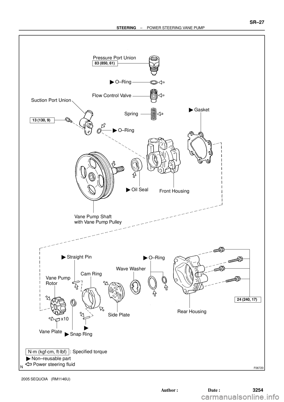
F06720
Pressure Port Union
83 (850, 61)
� O±Ring
Flow Control Valve
Spring
� O±Ring
Suction Port Union
13 (130, 9)
Vane Pump Shaft
with Vane Pump Pulley
� Oil Seal
Front Housing
� Gasket
24 (240, 17)
Rear Housing
� O±Ring
Wave Washer
Side Plate
Cam Ring
� Straight Pin
Vane Pump
Rotor
�
� Snap Ring x10Vane Plate
N´m (kgf´cm, ft´lbf): Specified torque
� Non±reusable part
Power steering fluid
± STEERINGPOWER STEERING VANE PUMP
SR±27
3254 Author�: Date�:
2005 SEQUOIA (RM1146U)
Page 3468 of 4323
(3.4W) Fuel Gauge
Z05730
Warning Light
Ignition
Switch
Battery
1
23
45
Wire
Harness Side:
I28772
I01278
BE±56
± BODY ELECTRICALCOMBINATION METER
346")
I21530
Ignition
Switch
Battery(Wire Harness Side)(3.4W) Fuel Gauge
Z05730
Warning Light
Ignition
Switch
Battery
1
23
45
Wire
Harness Side:
I28772
I01278
BE±56
± BODY ELECTRICALCOMBINATION METER
3460 Author�: Date�:
2005 SEQUOIA (RM1146U)
(c) Connect terminals 2 and 3 on the wire harness side con-
nector through a 3.4 watts test bulb.
(d) Turn the ignition switch ON, check that the bulb comes on
and the receiver gauge needle moves towards the full
side.
HINT:
Because of silicon oil in the gauge, it will take a short time for
the needle to stabilize.
If operation is not as specified, inspect the receiver gauge resis-
tance.
4. INSPECT FUEL LEVEL WARNING LIGHT OPERATION
(a) Disconnect the connector from the sender gauge.
(b) Connect terminals 2 and 3 on the wire harness side con-
nector.
(c) Turn the ignition switch ON and check that the warning
light comes on.
If the warning light does not come on, test the bulb or inspect
the wire harness.
5. INSPECT ENGINE COOLANT TEMPERATURE SEND-
ER GAUGE RESISTANCE
(a) Disconnect the engine coolant temperature sender
gauge.
(b) Measure the resistance between terminals 1 and 2 of the
connector according to the value(s) in the table below.
Temperature °C (°F)Resistance (W)
±20 (±4)13,840 to 16,330
20 (68)2,320 to 2,590
80 (176)310 to 326
110 (230)139.9 to 143.5
If resistance value is not as specified, replace the engine cool-
ant sender gauge.
6. INSPECT OIL PRESSURE SENDER OPERATION
(a) Disconnect the connector from the oil pressure sender.
(b) Check that no continuity exists between terminal and
ground with the engine stopped.
(c) Check that continuity exists between terminal and ground
with the engine running.
HINT:
Oil pressure should be over 24.5 kPa (0.25 kgf/cm
2, 3.55 psi).
If operation is not as specified, replace the oil pressure sender.
Page 3569 of 4323
Hole Here BO±8
± BODYHOOD SUPPORT
3561 Author�: Date�:
2005 SEQUOIA (RM1146U)
HOOD SUPPORT
REPLACEMENT
1. REMOVE HOOD SUPPORT
(a) Remove the bolt and hood support")
BO45K±01
H04840
150 mm (5.91 in.)Hole Here BO±8
± BODYHOOD SUPPORT
3561 Author�: Date�:
2005 SEQUOIA (RM1146U)
HOOD SUPPORT
REPLACEMENT
1. REMOVE HOOD SUPPORT
(a) Remove the bolt and hood support from the hood.
HINT:
While supporting the hood by hand, remove the hood support
from the hood.
(b) Remove the bolt and hood support.
2. IF NECESSARY, REPLACE HOOD SUPPORT
NOTICE:
Handling the hood support
�Do not disassemble the support as the cylinder is
filled with pressurized gas.
�If the hood support is to be replaced, drill a 2.0 ± 3.0
mm (0.079 ± 0.118 in.) hole in the area shown in the il-
lustration to completely release the high pressure
gas before disposing of it.
�When drilling, chips may fly out so work carefully.
�The gas is colorless, odorless and non ± toxic.
�When working, handle the hood support carefully.
Never score or scratch the exposed part of the piston
rod, and allow any paint or oil to get on it.
�Do not turn the piston rod and cylinder with the hood
support fully extended.
3. INSTALL HOOD SUPPORT
(a) Install the bolt and hood support to the body.
Torque: 22 N´m (224 kgf´cm, 16 ft´lbf)
(b) Install the bolt and hood support to the hood.
Torque: 22 N´m (224 kgf´cm, 16 ft´lbf)
Page 3594 of 4323

± BODYBACK DOOR STAY
BO±33
3586 Author�: Date�:
2005 SEQUOIA (RM1146U)
BACK DOOR STAY
REPLACEMENT
1. REMOVE BACK DOOR STAY
(a) Slide the clip, then remove the ba")
BO45X±01
H17899
150 mm (5.91 in.)
± BODYBACK DOOR STAY
BO±33
3586 Author�: Date�:
2005 SEQUOIA (RM1146U)
BACK DOOR STAY
REPLACEMENT
1. REMOVE BACK DOOR STAY
(a) Slide the clip, then remove the back door stay from the
back door.
HINT:
While supporting the back door with your hand, remove the
back door stay.
(b) Slide the clip, then remove the bolts and back door stay
from the body.
2. IF NECESSARY, REPLACE BACK DOOR STAY
NOTICE:
When handling the back door stay.
�Do not disassemble the back door stay because the
cylinder is filled with pressurized gas.
�If the back door stay is to be replaced, drill a 2.0 ± 3.0
mm (0.079 ± 0.118 in.) hole in the bottom of the back
door stay as shown in the illustration to completely
release the high±pressure gas before disposing of it.
�When drilling, chips may fly out so work carefully.
�The gas is colorless, odorless and non±toxic.
�When working, handle the back door stay carefully.
Never score or scratch the exposed part of the piston
rod, and never allow paint or oil to get on it.
�Do not turn the piston rod and cylinder with the back
door stay fully extended.
3. INSTALL BACK DOOR STAY
(a) Install the bolts and back door stay to the body.
Torque: 19 N´m (195 kgf´cm, 14 ft´lbf)
(b) Install the bolts and back door stay to the back door.
Torque: 19 N´m (195 kgf´cm, 14 ft´lbf)
Page 3736 of 4323

AIR CONDITIONING SYSTEM
PRECAUTION
1. DO NOT HANDLE")
AC2810
AC1JS±06
AC2811
N11084
Wrong Okay
HI LO HILO
± AIR CONDITIONINGAIR CONDITIONING SYSTEM
AC±1
3728 Author�: Date�:
2005 SEQUOIA (RM1146U)
AIR CONDITIONING SYSTEM
PRECAUTION
1. DO NOT HANDLE REFRIGERANT IN AN ENCLOSED
AREA OR NEAR AN OPEN FLAME
2. ALWAYS WEAR EYE PROTECTION
3. BE CAREFUL NOT TO GET LIQUID REFRIGERANT IN
YOUR EYES OR ON YOUR SKIN
If liquid refrigerant gets in your eyes or on your skin.
(a) Wash the area with lots of cool water.
CAUTION:
Do not rub your eyes or skin.
(b) Apply clean petroleum jelly to the skin.
(c) Go immediately to a physician or hospital for professional
treatment.
4. NEVER HEAT CONTAINER OR EXPOSE IT TO OPEN
FLAME
5. BE CAREFUL NOT TO DROP CONTAINER OR NOT TO
APPLY PHYSICAL SHOCKS TO IT
6. DO NOT OPERATE COMPRESSOR WITHOUT
ENOUGH REFRIGERANT IN REFRIGERATION SYS-
TEM
If there is not enough refrigerant in the refrigerant system, oil lu-
brication will be insufficient and compressor burnout may occur.
Necessary care should be taken to avoid this.
7. DO NOT OPEN PRESSURE MANIFOLD VALVE WHILE
COMPRESSOR IS OPERATING
If the high pressure valve is opened, refrigerant flows in the re-
verse direction and could cause the charging cylinder to rup-
ture, so open and close only the low pressure valve.
8. BE CAREFUL NOT TO OVERCHARGE SYSTEM WITH
REFRIGERANT
If refrigerant is overcharged, it causes problems such as insuffi-
cient cooling, poor fuel economy, engine overheating, etc.
Page 3742 of 4323

I22614
Condition: Insufficient cooling
Single A/C:
Dual A/C:
I22614
Condition: Insufficient cooling
Single A/C:
Dual A/C:
NOTE: These indications
are shown when the refrig-
eration system has been
opened and the refrigerant
has been charged without
vacuum purging.
± AIR CONDITIONINGAIR CONDITIONING SYSTEM
AC±7
3734 Author�: Date�:
2005 SEQUOIA (RM1146U)
(6) Refrigerant overcharged or insufficient cooling of
condenser
Symptom seen in
refrigeration systemProbable causeDiagnosisRemedy
� Pressure too high on both low
and high pressure sides
� No air bubbles seen through the
sight glass even when the engine
rpm is lowered� Unable to develop sufficient per-
formance due to excessive refrig-
erant
� Insufficient cooling of condenser� Excessive refrigerant in
cycle"refrigerant overcharged
� Condenser cooling
insufficient"condenser fins
clogged or cooling fan faulty
(1) Clean condenser
(2) Check cooling fan with fluid
coupling operation
(3) If (1) and (2) are in normal
state, check amount of refrigerant
and charge proper amount of re-
frigerant
(7) Air present in refrigeration system
Symptom seen in
refrigeration systemProbable causeDiagnosisRemedy
� Pressure too high on both low
and high pressure sides
� The low pressure piping hot to
the touch
� Bubbles seen in sight glass
Air in refrigeration system
� Air present in refrigeration sys-
tem
� Insufficient vacuum purging
(1) Check compressor oil to see if
it is dirty or insufficient
(2) Evacuate air and charge new
refrigerant
Page 3828 of 4323
AC1LT±05
I21452
± AIR CONDITIONINGPRESSURE SWITCH
AC±93
3820 Author�: Date�:
2005 SEQUOIA (RM1146U)
REMOVAL
1. DISCHARGE REFRIGERANT FROM REFRIGERATION
SYSTEM
HINT:
At the time of installation, refer to the following:
�Evacuate air from the refrigeration system.
�Charge the system with refrigerant and inspect for leak-
age of refrigerant.
Specified amount:
Single A/C: 750 ± 50 g (26.45 ± 1.76 oz.)
Dual A/C: 1050 ± 50 g (37.03 ± 1.76 oz.)
2. REMOVE PRESSURE SWITCH FROM LIQUID TUBE
Disconnect the connector and remove the pressure switch.
Torque: 10 N´m (100 kgf´cm, 7 ft´lbf)
HINT:
�Being careful not to deform the tube, lock the switch
mounted on the tube with an open end wrench and re-
move the switch.
�At the time of installation, refer to the following:
Lubricate a new O±ring with the compressor oil and install
it to the switch.