Page 182 of 4323
 Stabilizer bar x Stabilizer bar link
1919014
Stabilizer bar bracket x Chassis frame3737727
( ) For use")
SS±40
± SERVICE SPECIFICATIONSSUSPENSION AND AXLE
182 Author�: Date�:
2005 SEQUOIA (RM1146U) Stabilizer bar x Stabilizer bar link
1919014
Stabilizer bar bracket x Chassis frame3737727
( ) For use with SST
Part tightenedN´mkgf´cmft´lbf
REAR AXLE
Hub nut11 01,12283
Backing plate x Brake caliper1051,07077
Parking brake cable x Backing plate8.08271 in.´lbf
Axle housing x Backing plate1221,24490
Brake line union nut15.515811
ABS speed sensor x Axle housing8.08271 in.´lbf
REAR DIFFERENTIAL
Differential x Propeller shaft7475056
Drive pinion x Companion flangeSee page SA±113
Companion flange x Stud bolt101027.4
Differential carrier x Axle housing7374054
Differential carrier x Bearing cap11 31,15083
Differential case x Ring gear1251,27092
Drain plug4950036
Filler plug4950036
REAR SUSPENSION
Shock absorber x Chassis frame5859143
Shock absorber x Axle housing8788764
REAR LATERAL CONTROL ROD
Lateral control rod x Chassis frame1401,428103
Lateral control rod x Axle housing1301,32696
REAR UPPER AND LOWER CONTROL ARM
Upper control arm x Chassis frame1401,428103
Upper control arm x Axle housing1401,428103
Upper control arm x Brake line bracket2828621
Lower control arm x Chassis frame1301,32696
Lower control arm x Axle housing1301,32696
Lower control arm x Parking brake cable bracket2626519
REAR STABILIZER BAR
Bracket x Axle housing3737727
Stabilizer bar link x Chassis frame6970451
Stabilizer bar x Stabilizer bar link6970451
HEIGHT CONTROL COMPRESSOR AND DRYER
Height control compressor x Bracket2930021
Height control filter x Height control compressor6.46557 in.´lbf
Bracket x Body2930021
HEIGHT CONTROL VALVE
Height control set bolt2930021
Page 737 of 4323

ROAD TEST
1. PROBLEM SYMPTOM CONFIRMATION
Based on the result of the customer problem analysis, try")
DIDIQ±01
± DIAGNOSTICSAUTOMATIC TRANSMISSION
DI±535
729 Author�: Date�:
2005 SEQUOIA (RM1146U)
ROAD TEST
1. PROBLEM SYMPTOM CONFIRMATION
Based on the result of the customer problem analysis, try to reproduce the symptoms. If the problem is that
the transaxle does not shift up, shift down, or the shift point is too high or too low, conduct the following road
test referring to the automatic shift schedule and simulate the problem symptoms.
2. ROAD TEST
NOTICE:
Perform the test at the normal operating ATF (Automatic Transmission Fluid) temperature: 50 to 80°C
(122 to 176°F).
(a) D position test:
Shift into the D position and fully depress the accelerator pedal and check the following points. Check
up±shift operation.
(1) Check up±shift operation.
Check that 1 " 2, 2 " 3, 3 " 4 and 4 " 5th up±shifts take place, and that the shift points conform
to the automatic shift schedule (See page SS±24).
HINT:
5th Gear Up±shift Prohibition Control
�Engine coolant temperature is 55 °C (131 °F) or less and vehicle speed is at 51 km/h (32 mph) or less.
4th Gear Up±shift Prohibition Control
�Engine coolant temperature is 40 °C (104 °F) or less and vehicle speed is at 45 km/h (28 mph) or less.
5th Gear Lock±up Prohibition Control
�Brake pedal is depressed.
�Accelerator pedal is released.
�Engine coolant temperature is 60 °C (140 °F) or less.
(2) Check for shift shock and slip.
Check for shock and slip at the 1 " 2, 2 " 3, 3 " 4 and 4 " 5th up±shifts.
(3) Check for abnormal noise and vibration.
Check for abnormal noise and vibration when up±shifting from 1 " 2, 2 " 3, 3 " 4 and 4 " 5
while driving with the shift lever in the D position, and check while driving in the lock±up condition.
HINT:
The check for the cause of abnormal noise and vibration must be done thoroughly as it could also be due
to loss of balance in the differential, torque converter clutch, etc.
(4) Check kick±down operation.
Check vehicle speeds when the 2nd to 1st, 3rd to 2nd, 4th to 3rd, and 5th to 4th kick±downs take
place while driving with the shift lever in the D position. Confirm that each speed is within the
applicable vehicle speed range indicated in the automatic shift schedule (See page SS±24).
(5) Check abnormal shock and slip at kick±down.
(6) Check the lock±up mechanism.
�Drive in the D position (5th gear), at a steady speed (lock±up ON).
�Lightly depress the accelerator pedal and check that the engine speed does not change
abruptly.
HINT:
If there is a big jump in engine speed, there is no lock±up.
Page 1179 of 4323
± DIAGNOSTICSABS WITH EBD & BA & TRAC & VSC SYSTEM
DI±977
1171 Author�: Date�:
2005 SEQUOIA (RM1146U)
DTC C1340 / 47 Center DIFF. Lock Circuit Malfunction
CIRCUIT DESCRIPTION
This circuit sends the signal to the ECU by detecting that the transfer center differential is in the ºLOCKº posi-
tion.
DTC No.DTC Detecting ConditionTrouble Area
C1340 / 47Center diff. lock position switch signal does not change
�Center diff. lock position switch
�Center diff. lock position switch circuit
�Center diff. lock Indicator light circuit
�Translate ECU
DIDMD±01
Page 1182 of 4323
DI±980
± DIAGNOSTICSABS WITH EBD & BA & TRAC & VSC SYSTEM
1174 Author�: Date�:
2005 SEQUOIA (RM1146U)
INSPECTION PROCEDURE
1 Check center differential lock operation (See page TR±39).
OK:
Center differential lock operation is norm.
NG Repair or replace one±touch 2±4 selector sys-
tem.
OK
2 Check operation of the center differential lock indicator light.
PREPARATION:
(a) Turn the ignition switch to the ON position.
(b) Set the transfer to the L4 position.
CHECK:
Check that pressing the center differential lock switch locks the differential and turns the lock indicator on.
OK:
Indicator light: ON/OFF or OFF/ON
HINT:
When the center differential cannot be shifted to LOCK smoothly, the center differential lock indicator light
will blink.
NG Repair or replace center differential lock indica-
tor light circuit.
OK
3 Check that the 4WD ECU connectors are securely connected to the 4WD ECU.
NO Connect the connector to the 4WD ECU.
YES
Page 1266 of 4323

SYSTEM DESCRIPTION
1. BRIEF DESCRIPTION
(a) The CAN (Controller Area Network) is a serial data c")
DIDI0±01
DI±1064
± DIAGNOSTICSCAN COMMUNICATION SYSTEM
1258 Author�: Date�:
2005 SEQUOIA (RM1146U)
SYSTEM DESCRIPTION
1. BRIEF DESCRIPTION
(a) The CAN (Controller Area Network) is a serial data communication system for real time application.
It is an in±vehicle multiplex communication system that has a high communication speed (500 kbps)
and the function to detect malfunctions.
(b) By pairing the CANH and CANL bus lines, the CAN performs communication based on differential volt-
age.
(c) Many ECUs (sensors) installed in the vehicle operate by sharing information and communicating with
each other.
(d) The CAN has two resistors of 120 W which are necessary to communicate with the main bus line.
2. DEFINITION OF TERMS
(a) Main bus line
(1) The main bus line is a wire harness between the two terminus circuits on the bus (communication
line). This is the main bus in the CAN communication system.
(b) Sub bus line
(1) The sub bus line is a wire harness that diverges from the main bus line to the ECU.
3. ECUs THAT COMMUNICATE THROUGH CAN COMMUNICATION SYSTEM
(a) Translate ECU
(b) Suspension Control ECU
(c) ECM
4. DIAGNOSTIC CODE FOR CAN COMMUNICATION SYSTEM
DTCs for the CAN communication system are as follows:
U0100/65, U0122/67, U0132/72, 65, 94.
HINT:
If C1201/51, C1202/52 or C1203/53 is output from skid control ECU, perform troubleshooting of each diag-
nosis code (see page DI±921).
5. REMARK FOR TROUBLESHOOTING
(a) Trouble in the CAN bus (communication line) can be checked from the DLC3 (except when there is
a wire break in lines other than the sub bus line of the DLC3).
NOTICE:
Do not insert the tester directly into the DLC3 connector. Be sure to use a service wire.
(b) The CAN communication system cannot detect trouble in the sub bus line of the DLC3 even though
the DLC3 is also connected to the CAN communication system.
6. HOW TO DISTINGUISH THE CAN J/C CONNECTOR
In the CAN communication system, all connectors connected to the CAN J/C are the same shape. The con-
nectors connected to the CAN J/C can be distinguished by the colors of the bus lines.
HINT:
See ºTERMINALS OF ECUº (see page DI±1068) for bus line colors.
Page 2948 of 4323

TROUBLESHOOTING
PROBLEM SYMPTOMS TABLE
Use the table below to help find the cause of the problem. The numbers i")
TR04H±04
TR±2
± TRANSFERTROUBLESHOOTING
2940 Author�: Date�:
2005 SEQUOIA (RM1146U)
TROUBLESHOOTING
PROBLEM SYMPTOMS TABLE
Use the table below to help find the cause of the problem. The numbers indicate the priority of the likely cause
of the problem. Check each part in order. If necessary, replace these parts.
SymptomSuspected AreaSee page
Noise
1. Oil (Level low)
2. Oil (Wrong)
3. Transfer faultyTR±5
TR±5
TR±7
Oil leakage
1. Oil (Level too high)
2. Gasket (Damaged)
3. Oil seal (Worn or damaged)
4. O±ring (Worn or damaged)TR±5
TR±7
TR±16
TR±7
Tight corner brakingCenter differential or transfer faultyTR±7
Shift from 2WD (H) to 4WD (H) impossible
1. 4WD fuse
2. Wire harness
3. Vehicle speed sensor
4. 2WD/4HI switch
5. 4WD indicator light
6. Actuator assembly
7. A.D.D. control system
8. 4WD control ECU
9. Transfer assembly±
±
BE±55
TR±39
TR±39
TR±39
SA±61
TR±39
TR±3
Shift from 2WD (H) to 4WD (L4) impossible
1. 4LO switch
2. Wire harness
3. 4WD control ECUTR±39
±
TR±39
Shift from 4WD (H) to 4WD (L4) impossible
1. 4LO switch
2. Wire harness
3. 4WD control ECUTR±9
±
TR±39
Shift from 4WD (H) to 2WD (H) impossible
1. 4WD fuse
2. Wire harness
3. 4WD indicator light
4. Actuator assembly
5. A.D.D. control system
6. 4WD control ECU
7. Transfer assembly±
±
TR±39
TR±39
SA±61
TR±39
TR±3
Shift from 4WD (L4) to 2WD (H) impossible
1. 2WD/4HI switch
2. Wire harness
3. 4WD control ECUTR±39
±
TR±39
Shift from 4WD (L4) to 4WD (H) impossible
1. 2WD/4HI switch
2. Wire harness
3. 4WD control ECUTR±39
±
TR±39
Page 2972 of 4323
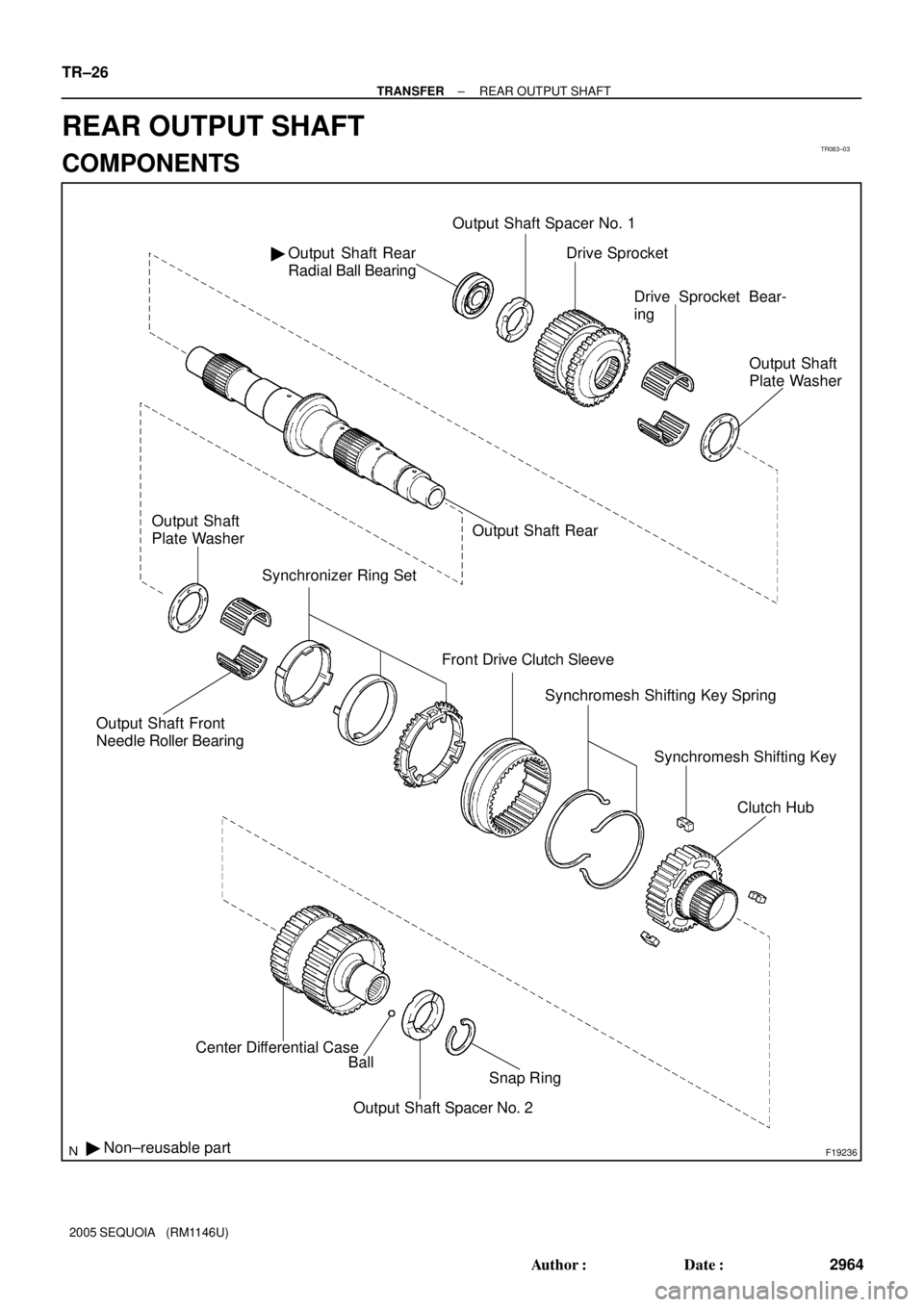
TR083±03
F19236
Output Shaft Rear
Radial Ball Bearing �Output Shaft Spacer No. 1
Output Shaft Front
Needle Roller Bearing
Synchronizer Ring Set
Front Drive Clutch Sleeve
� Non±reusable partCenter Differential Case
Ball
Snap Ring
Output Shaft Spacer No. 2Drive Sprocket
Drive Sprocket Bear-
ing
Output Shaft
Plate Washer
Output Shaft Rear Output Shaft
Plate Washer
Synchromesh Shifting Key Spring
Synchromesh Shifting Key
Clutch Hub
TR±26
± TRANSFERREAR OUTPUT SHAFT
2964 Author�: Date�:
2005 SEQUOIA (RM1146U)
REAR OUTPUT SHAFT
COMPONENTS
Page 2973 of 4323

DISASSEMBLY
1. INSPECT DRIVE SPROCKET THRUST CLEARANCE
Using a feeler gauge, mea")
TR0DH±01
F19276
F19277
F19278
F19279
± TRANSFERREAR OUTPUT SHAFT
TR±27
2965 Author�: Date�:
2005 SEQUOIA (RM1146U)
DISASSEMBLY
1. INSPECT DRIVE SPROCKET THRUST CLEARANCE
Using a feeler gauge, measure the thrust clearance of the drive
sprocket.
Standard clearance:
0.15 to 0.24 mm (0.0059 to 0.0094 in.)
Maximum clearance:
0.24 mm (0.0094 in.)
If the clearance exceeds the maximum, replace the drive
sprocket.
2. INSPECT DRIVE SPROCKET RADIAL CLEARANCE
Using a dial indicator, measure the radial clearance of the drive
sprocket.
Standard clearance:
0.01 to 0.06 mm (0.0004 to 0.0024 in.)
Maximum clearance:
0.06 mm (0.0024 in.)
If the clearance exceeds the maximum, replace the drive
sprocket, output shaft rear or needle roller bearing.
3. REMOVE CENTER DIFFERENTIAL CASE
(a) Using a snap ring expander, remove the snap ring.
(b) Remove the output shaft spacer No. 2 and ball.
(c) Remove the center differential case.
4. REMOVE CLUTCH HUB
Remove the clutch hub, output shaft front needle roller bearing
and output shaft plate washer.