Page 2777 of 4323
SF0P0±14
BO0919
Crack Leakage
Deformation
FU0041
Pipe
Clip 2 to 7 mm (0.08 to 0.28 in.)
0 to 3 mm (0 to 0.12 in.)
Hose
B17498
Fuel Inlet Hose
Clamp
0 to 3 mm
(0 to 0.12 in.)
Hose Clamp Area
± SFIFUEL TANK AND LINE
SF±35
2769 Author�: Date�:
2005 SEQUOIA (RM1146U)
INSPECTION
INSPECT FUEL TANK AND LINE
(a) Check the fuel lines for cracks or leakage, and all connec-
tions for deformation.
(b) Check the fuel tank vapor vent system hoses and connec-
tions for looseness, sharp bends or damage.
(c) Check the fuel tank for deformation, cracks, fuel leakage
or tank band looseness.
(d) Check the filler neck for damage or fuel leakage.
(e) Hose and pipe connections are as shown in the illustra-
tion.
If a problem is found, repair or replace the parts as necessary.
Page 2778 of 4323
SF1XI±01
B17583
B17582
B17581
SF±36
± SFIFUEL TANK AND LINE
2770 Author�: Date�:
2005 SEQUOIA (RM1146U)
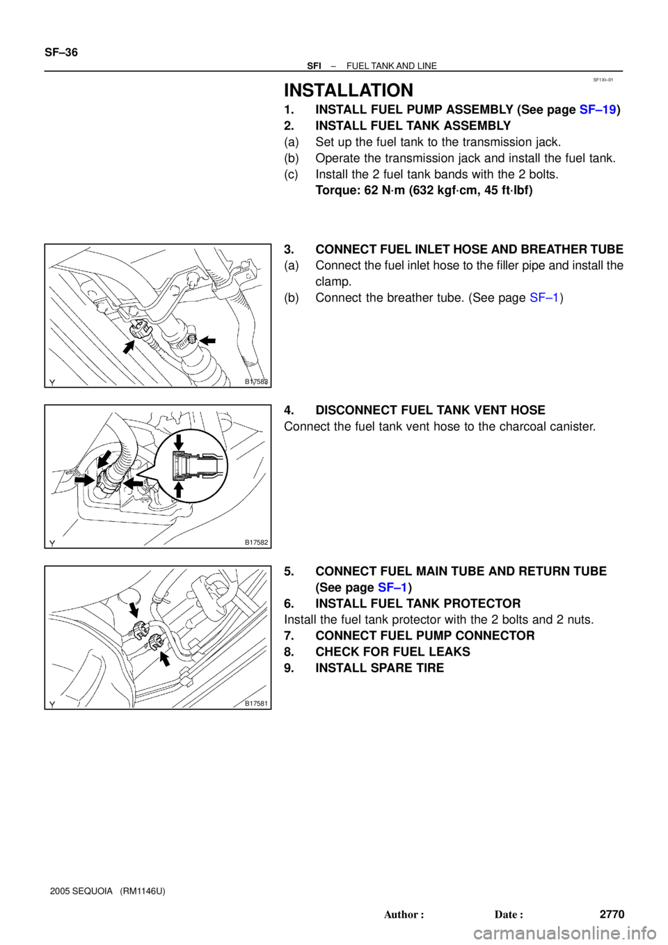
INSTALLATION
1. INSTALL FUEL PUMP ASSEMBLY (See page SF±19)
2. INSTALL FUEL TANK ASSEMBLY
(a) Set up the fuel tank to the transmission jack.
(b) Operate the transmission jack and install the fuel tank.
(c) Install the 2 fuel tank bands with the 2 bolts.
Torque: 62 N´m (632 kgf´cm, 45 ft´lbf)
3. CONNECT FUEL INLET HOSE AND BREATHER TUBE
(a) Connect the fuel inlet hose to the filler pipe and install the
clamp.
(b) Connect the breather tube. (See page SF±1)
4. DISCONNECT FUEL TANK VENT HOSE
Connect the fuel tank vent hose to the charcoal canister.
5. CONNECT FUEL MAIN TUBE AND RETURN TUBE
(See page SF±1)
6. INSTALL FUEL TANK PROTECTOR
Install the fuel tank protector with the 2 bolts and 2 nuts.
7. CONNECT FUEL PUMP CONNECTOR
8. CHECK FOR FUEL LEAKS
9. INSTALL SPARE TIRE
Page 2793 of 4323
B17490
N´m (kgf´cm, ft´lbf) : Specified torque
�Gasket
Non±reusable part�
18 (185, 13)
VSV Connector for
EVAP Injector Connector
Fuel Return Hose VSV ConnectorEngine Wire
Engine Wire
Throttle Body
Connector
18 (185, 13)
Injector Connector VSV Connector
18 (185, 13)
Engine Wire
± SFIACOUSTIC CONTROL INDUCTION SYSTEM (ACIS)
SF±51
2785 Author�: Date�:
2005 SEQUOIA (RM1146U)
Page 2801 of 4323
SF1XT±01
B07643
Continuity
2 1 Ohmmeter
Ohmmeter
3
No Continuity5
B07644
2 1
Ohmmeter
3 4
Battery
Continuity
± SFIFUEL PUMP RELAY
SF±59
2793 Author�: Date�:
2005 SEQUOIA (RM1146U)
FUEL PUMP RELAY
INSPECTION
1. REMOVE RELAY BOX COVER
2. REMOVE FUEL PUMP RELAY (Marking: F/P)
3. INSPECT FUEL PUMP RELAY CONTINUITY
(a) Using an ohmmeter, check that there is continuity be-
tween terminals 1 and 2.
If there is no continuity, replace the relay.
(b) Check that there is continuity between terminals 3 and 4.
If there is no continuity, replace the relay.
4. INSPECT FUEL PUMP RELAY OPERATION
(a) Apply battery positive voltage across terminals 1 and 2.
(b) Using an ohmmeter, check that there is no continuity be-
tween terminals 3 and 4.
If there is continuity, replace the relay.
5. REINSTALL FUEL PUMP RELAY
6. REINSTALL RELAY BOX COVER
Page 2802 of 4323
SF138±05
B17500
Fuel Pump Resistor
8.0 (82, 71 in.´lbf)
N´m (kgf´cm, ft´lbf) : Specified torque
SF±60
± SFIFUEL PUMP RESISTOR
2794 Author�: Date�:
2005 SEQUOIA (RM1146U)
FUEL PUMP RESISTOR
COMPONENTS
Page 2803 of 4323
SF139±05
B17501
Ohmmeter
± SFIFUEL PUMP RESISTOR
SF±61
2795 Author�: Date�:
2005 SEQUOIA (RM1146U)
INSPECTION
1. REMOVE FUEL PUMP RESISTOR
2. INSPECT FUEL PUMP RESISTOR
Using an ohmmeter, measure the resistance between the ter-
minals.
Resistance: 0.70 to 0.76 W at 20°C (68°F)
If the resistance is not as specified, replace the resistor.
3. REINSTALL FUEL PUMP RESISTOR
Torque: 8.0 N´m (82 kgf´cm,71 in.´lbf)
Page 2809 of 4323
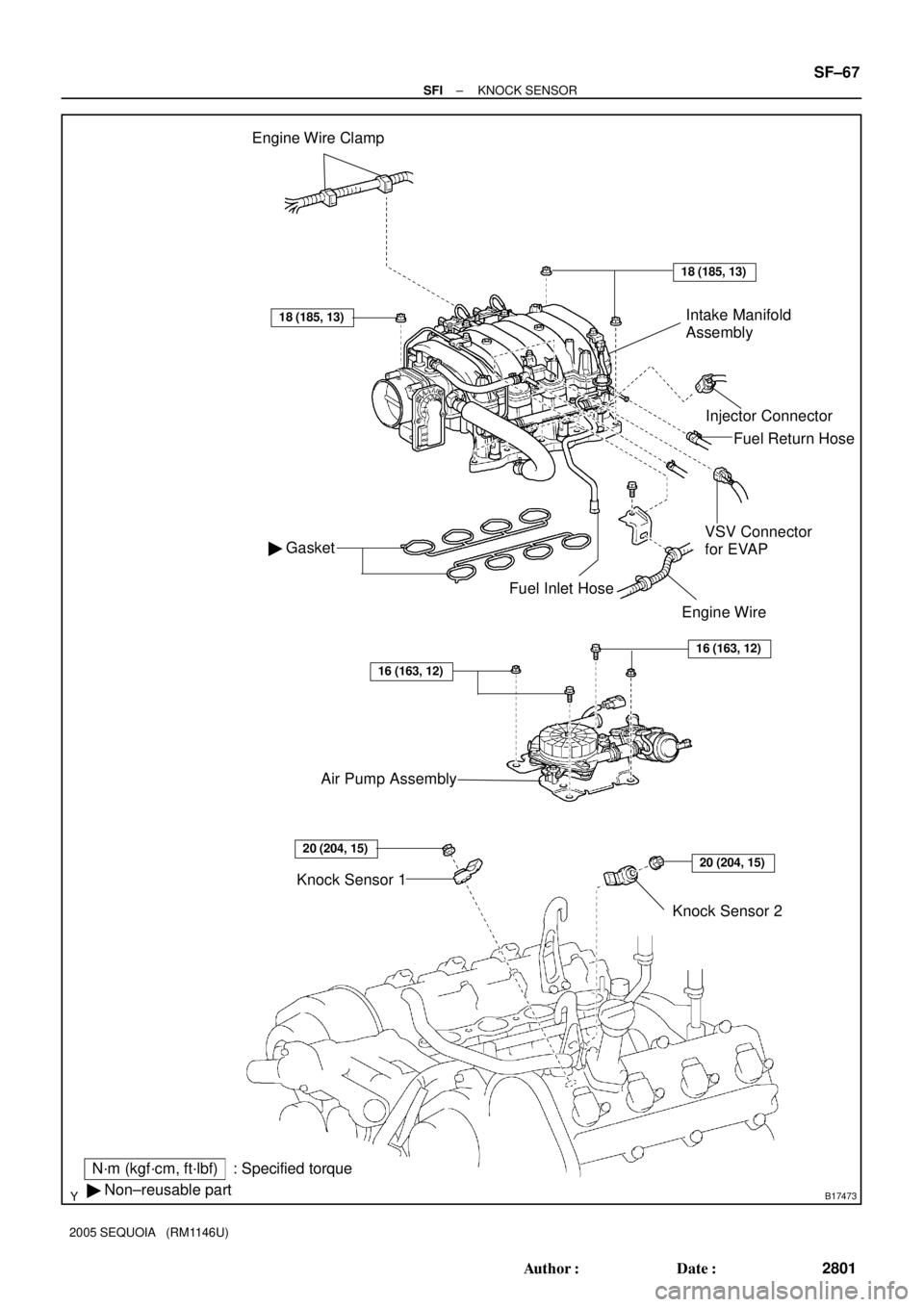
B17473
Engine Wire Clamp
Injector Connector
� Gasket
18 (185, 13)
N´m (kgf´cm, ft´lbf): Specified torque
� Non±reusable part
18 (185, 13)
Knock Sensor 2
VSV Connector
for EVAP
Fuel Inlet Hose
Knock Sensor 1Fuel Return Hose
Intake Manifold
Assembly
Engine Wire
20 (204, 15)20 (204, 15)
Air Pump Assembly
16 (163, 12)
16 (163, 12)
± SFIKNOCK SENSOR
SF±67
2801 Author�: Date�:
2005 SEQUOIA (RM1146U)
Page 2811 of 4323
SF1XV±01
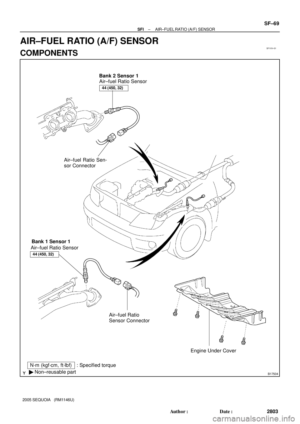
B17504
N´m (kgf´cm, ft´lbf)
� Non±reusable part: Specified torqueAir±fuel Ratio Sensor
Engine Under Cover Bank 2 Sensor 1
Bank 1 Sensor 1
Air±fuel Ratio
Sensor Connector Air±fuel Ratio Sensor
44 (450, 32)
Air±fuel Ratio Sen-
sor Connector
44 (450, 32)
± SFIAIR±FUEL RATIO (A/F) SENSOR
SF±69
2803 Author�: Date�:
2005 SEQUOIA (RM1146U)
AIR±FUEL RATIO (A/F) SENSOR
COMPONENTS

0 to 3 mm (0 to 0.12 in.)
Hose
B17498
Fuel Inlet Hose
Clamp
0 to 3 mm
(0 to 0.12 in.)
Hose Clamp Area
± SFIFUE")