Page 2812 of 4323
 SENSOR
2804 Author�: Date�:
2005 SEQUOIA (RM1146U)
INSPECTION
1. INSPECT HEATER RESISTANCE OF")
SF1XW±01
B17505
+BHT
B17512
C2 C1
A2A±
A2A+
E1
B2 B3
B1 A1A+
A1A±
SF±70
± SFIAIR±FUEL RATIO (A/F) SENSOR
2804 Author�: Date�:
2005 SEQUOIA (RM1146U)
INSPECTION
1. INSPECT HEATER RESISTANCE OF AIR FUEL RATIO
SENSOR
(a) Disconnect the air fuel ratio sensor connector.
(b) Using an ohmmeter, measure the resistance between ter-
minals +B and HT.
Resistance 11 to 16 kW at 20°C (68°F)
If the resistance is not as specified, replace the sensor.
Torque: 44 N´m (450 kgf´cm, 32 ft´lbf)
(c) Reconnect the air fuel ratio sensor connector.
2. INSPECT OPERATION OF AIR FUEL RATIO SENSOR
(See page DI±88)
3. INSPECT AIR±FUEL RATIO COMPENSATION SYS-
TEM
(a) Measure the voltage between the terminals of the ECM
connectors.
Standard:
Tester ConnectionConditionSpecified Condition
B2±22 (A1A+)
± B1±1 (E1)Ignition switch ON3.3 V
B2±30 (A1A±)
± B1±1 (E1)Ignition switch ON2.9 V
B2±23 (A2A+)
± B1±1 (E1)Ignition switch ON3.3 V
B2±31 (A2A±)
± B1±1 (E1)Ignition switch ON2.9 V
NOTICE:
Connect test leads from the back side of the connector. The
connectors should not be disconnected from the ECM.
HINT:
The voltage between the terminals of the ECM is kept constant
regardless of the voltage of the A/F sensor.
Page 2813 of 4323

B17513
Air±fuel
Ratio
± SFIAIR±FUEL RATIO (A/F) SENSOR
SF±71
2805 Author�: Date�:
2005 SEQUOIA (RM1146U)
(b) C")
D13872
Hand±Held Tester
DLC3
CAN VIM
Rich Lean
Time14.6
3.3
Keep Engine Speed
(V)
B17513
Air±fuel
Ratio
± SFIAIR±FUEL RATIO (A/F) SENSOR
SF±71
2805 Author�: Date�:
2005 SEQUOIA (RM1146U)
(b) Connect a hand±held tester to the Controller Area Net-
work Vehicle Interface Module (CAN VIM). Then connect
the CAN VIM to the Date Link Connector 3 (DLC3).
(c) Turn the ignition switch ON.
(d) Select the following menu items : Data List / A/FS B1 S1
and O2S B1 S2.
(e) Warm up the A/F sensor by running the engine at 2,500
rpm for approximately 2 minutes.
(f) Keep the engine speed at 2,500 rpm and confirm that the
display of the ºA/FS B1 S1º is as shown in the illustration.
HINT:
�The illustration may slightly differ from the display on the
hand±held tester.
�The waveform of the A/F sensor is displayed only on the
hannd±heldtester .
(g) Confirm that the display of the ºO2S B1 S2º changes be-
tween 0 and 1 V with the engine speed at 2,500 rpm.
OK:
The voltage output oscillates more than 8 times in 10
seconds.
CAUTION:
�Perform the check immediately after warming up the
engine.
�If the voltage variation could not be verified, warm up
the heated oxygen sensor again. If it could not be veri-
fied even after warming up the sensor again, check
the DTC No. (See page DI±88)
Page 2817 of 4323
B17493
Engine Wire
VSV Connector
for Air Injection
System Engine Wire
Throttle Body
ConnectorFuel Return Hose
Engine WireInjector Connector
VSV Connector for
EVAP
VVT Sensor 2
N´m (kgf´cm, ft´lbf) : Specified torque
��
Non±reusable partGasket
VVT Sensor 1
VSV Connector
for ACIS
VVT Sensor ConnectorVVT Sensor Connector
18 (185, 13)
18 (185, 13)
7.5 (76, 66 in.´lbf)
± SFIVVT SENSOR
SF±75
2809 Author�: Date�:
2005 SEQUOIA (RM1146U)
Page 2824 of 4323
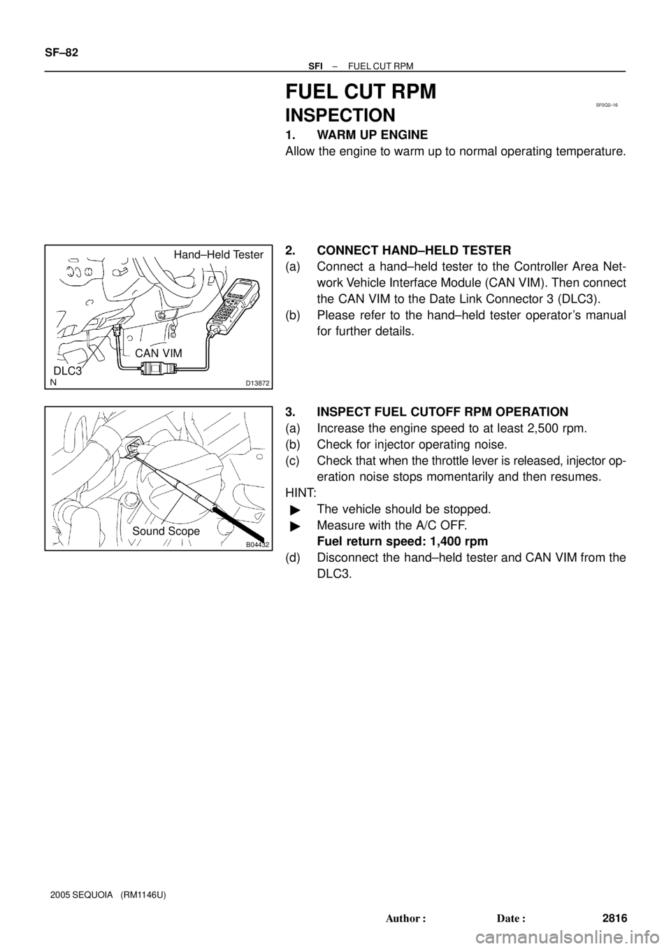
SF0Q2±16
D13872
Hand±Held Tester
DLC3
CAN VIM
B04432
Sound Scope
SF±82
± SFIFUEL CUT RPM
2816 Author�: Date�:
2005 SEQUOIA (RM1146U)
FUEL CUT RPM
INSPECTION
1. WARM UP ENGINE
Allow the engine to warm up to normal operating temperature.
2. CONNECT HAND±HELD TESTER
(a) Connect a hand±held tester to the Controller Area Net-
work Vehicle Interface Module (CAN VIM). Then connect
the CAN VIM to the Date Link Connector 3 (DLC3).
(b) Please refer to the hand±held tester operator's manual
for further details.
3. INSPECT FUEL CUTOFF RPM OPERATION
(a) Increase the engine speed to at least 2,500 rpm.
(b) Check for injector operating noise.
(c) Check that when the throttle lever is released, injector op-
eration noise stops momentarily and then resumes.
HINT:
�The vehicle should be stopped.
�Measure with the A/C OFF.
Fuel return speed: 1,400 rpm
(d) Disconnect the hand±held tester and CAN VIM from the
DLC3.
Page 2885 of 4323
B17496
Injector Connector
VSV Connector
for EVAP
Starter ConnectorStarterIntake Manifold Assembly Engine Wire and Clamp
� Gasket
� Non±reusable part
39 (400, 29)
Engine Wire
Protector
Fuel Return Hose
Engine Wire
N´m (kgf´cm, ft´lbf) : Specified torque� GasketFuel Inlet Hose
Air Switching Valve No.2
� Gasket
� Gasket
10 (102, 7 )
10 (102, 7 )
10 (102, 7 )
10 (102, 7 )
± STARTINGSTARTER
ST±3
2877 Author�: Date�:
2005 SEQUOIA (RM1146U)
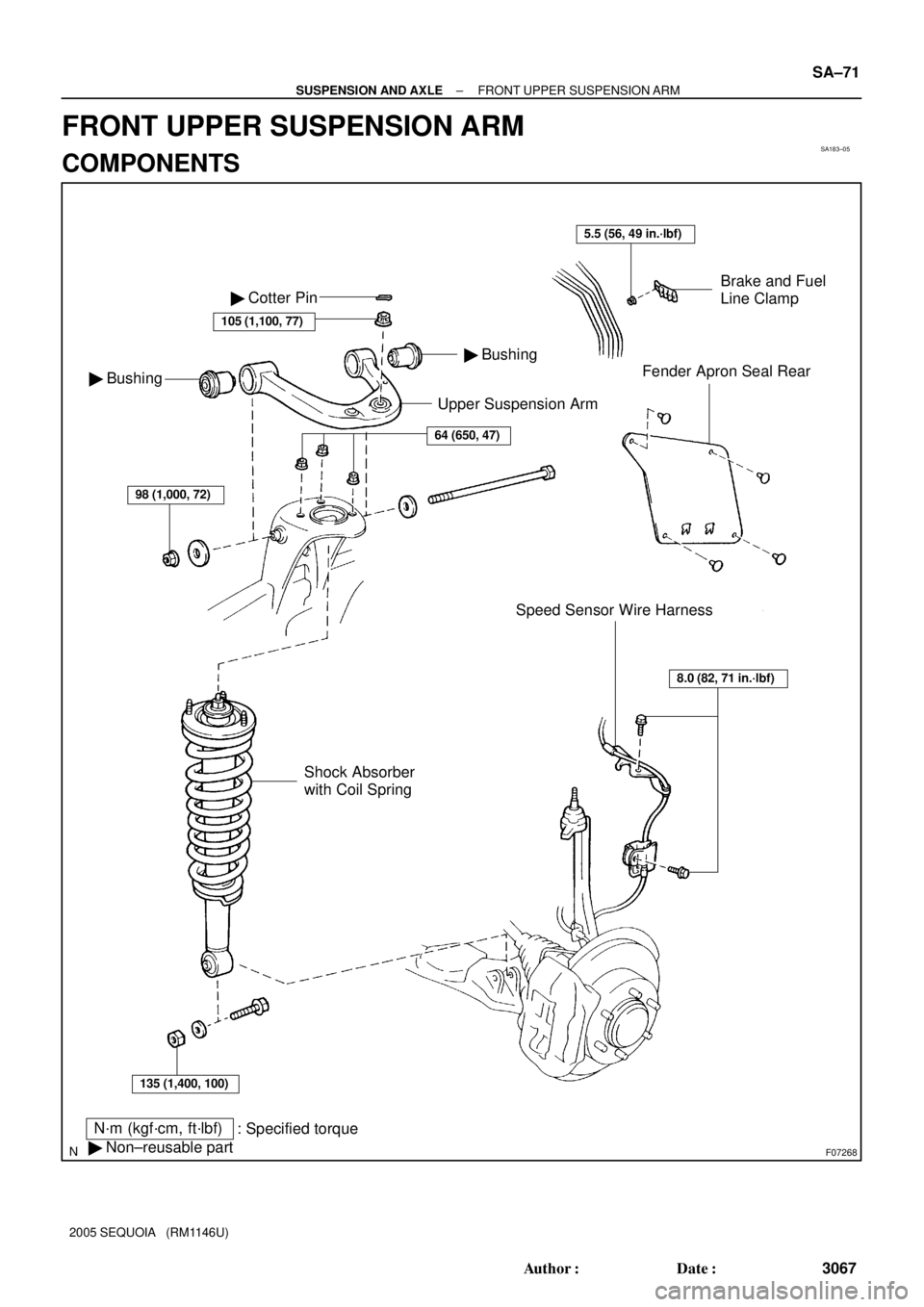
Page 3075 of 4323
SA183±05
F07268
Upper Suspension Arm
N´m (kgf´cm, ft´lbf)
: Specified torque
� Non±reusable part
Brake and Fuel
Line Clamp
Fender Apron Seal Rear
Speed Sensor Wire Harness � Bushing
� Bushing � Cotter Pin
105 (1,100, 77)
64 (650, 47)
98 (1,000, 72)
135 (1,400, 100)
Shock Absorber
with Coil Spring
8.0 (82, 71 in.´lbf)
5.5 (56, 49 in.´lbf)
± SUSPENSION AND AXLEFRONT UPPER SUSPENSION ARM
SA±71
3067 Author�: Date�:
2005 SEQUOIA (RM1146U)
FRONT UPPER SUSPENSION ARM
COMPONENTS
Page 3076 of 4323
SA23W±03
R13196
SST
F07269
F07270
SA±72
± SUSPENSION AND AXLEFRONT UPPER SUSPENSION ARM
3068 Author�: Date�:
2005 SEQUOIA (RM1146U)
REMOVAL
1. REMOVE SHOCK ABSORBER WITH COIL SPRING
(See page SA±64)
2. DISCONNECT SPEED SENSOR WIRE HARNESS
CLAMPS
Remove the 2 bolts and speed sensor wire harness clamps
from the steering knuckle and upper suspension arm.
3. DISCONNECT UPPER BALL JOINT
(a) Remove the cotter pin and loosen the nut.
(b) Using SST, disconnect the upper ball joint.
SST 09950±40011 (09951±04010, 09952±04010,
09953±04020, 09954±04010, 09955±04031,
09958±04011)
(c) Support the steering knuckle securely.
(d) Remove the nut.
4. REMOVE FENDER APRON SEAL REAR
Remove the 4 clips and fender apron seal rear.
5. REMOVE BRAKE AND FUEL LINE CLAMP
Disengage the 2 brake lines and fuel line, and remove the nut
and brake line clamp.
6. REMOVE UPPER SUSPENSION ARM
Remove the nut, bolt, 2 washers and upper suspension arm.
Page 3078 of 4323

INSTALLATION
1. INSTALL UPPER SUSPENSION ARM
Install the upper suspension arm with the 2")
SA187±06
SA±74
± SUSPENSION AND AXLEFRONT UPPER SUSPENSION ARM
3070 Author�: Date�:
2005 SEQUOIA (RM1146U)
INSTALLATION
1. INSTALL UPPER SUSPENSION ARM
Install the upper suspension arm with the 2 washers, bolt and nut.
Torque: 98 N´m (1,000 kgf´cm, 72 ft´lbf)
HINT:
After stabilizing the suspension, torque the nut.
2. INSTALL BRAKE AND FUEL LINE CLAMP
Torque: 5.5 N´m (56 kgf´cm, 49 in.´lbf)
3. INSTALL FENDER APRON SEAL REAR
4. CONNECT UPPER BALL JOINT
(a) Connect the upper ball joint to the upper suspension arm.
(b) Install the nut and a new cotter pin.
If the holes for the cotter pin are not aligned, tighten the nut further up to 60°.
Torque: 105 N´m (1,100 kgf´cm, 77 ft´lbf)
5. CONNECT SPEED SENSOR WIRE HARNESS CLAMPS
Torque: 8.0 N´m (82 kgf´cm, 71 in.´lbf)
6. INSTALL SHOCK ABSORBER WITH COIL SPRING (See page SA±70)
7. CHECK FRONT WHEEL ALIGNMENT (See page SA±4)
8. PERFORM ZERO POINT CALIBRATION OF STEERING ANGLE, MASTER CYLINDER PRES-
SURE, YAW RATE AND DECELERATION SENSORS (See page DI±897)
")