Page 2712 of 4323

A04856
FrontPort
A08472
LH Side
A05132
Push
Wire
Clamp
New
O±Ring
± ENGINE MECHANICALCYLINDER BLOCK
EM±125
2704 Author�: Date�:
2005 SEQUOIA (RM1146U)
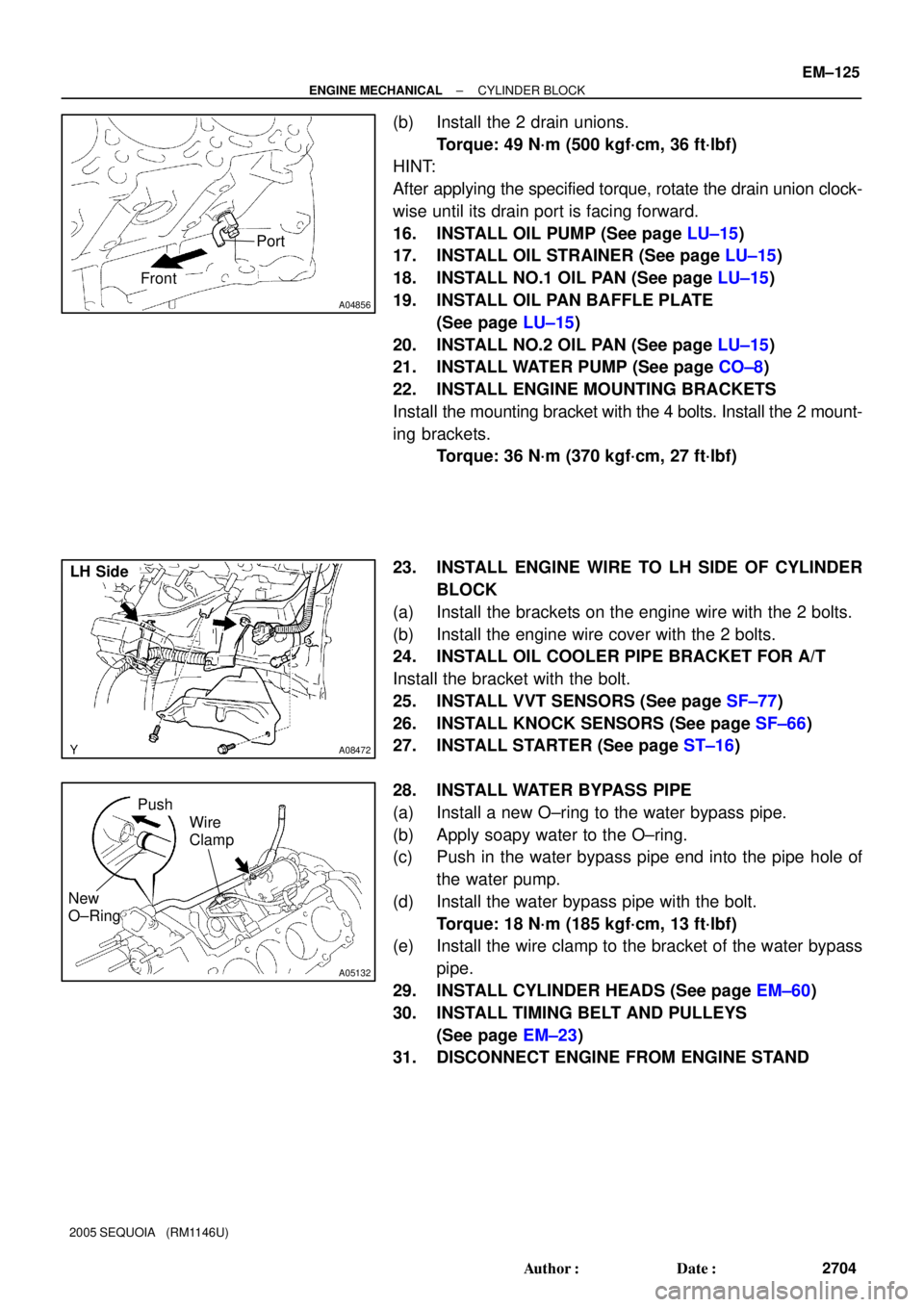
(b) Install the 2 drain unions.
Torque: 49 N´m (500 kgf´cm, 36 ft´lbf)
HINT:
After applying the specified torque, rotate the drain union clock-
wise until its drain port is facing forward.
16. INSTALL OIL PUMP (See page LU±15)
17. INSTALL OIL STRAINER (See page LU±15)
18. INSTALL NO.1 OIL PAN (See page LU±15)
19. INSTALL OIL PAN BAFFLE PLATE
(See page LU±15)
20. INSTALL NO.2 OIL PAN (See page LU±15)
21. INSTALL WATER PUMP (See page CO±8)
22. INSTALL ENGINE MOUNTING BRACKETS
Install the mounting bracket with the 4 bolts. Install the 2 mount-
ing brackets.
Torque: 36 N´m (370 kgf´cm, 27 ft´lbf)
23. INSTALL ENGINE WIRE TO LH SIDE OF CYLINDER
BLOCK
(a) Install the brackets on the engine wire with the 2 bolts.
(b) Install the engine wire cover with the 2 bolts.
24. INSTALL OIL COOLER PIPE BRACKET FOR A/T
Install the bracket with the bolt.
25. INSTALL VVT SENSORS (See page SF±77)
26. INSTALL KNOCK SENSORS (See page SF±66)
27. INSTALL STARTER (See page ST±16)
28. INSTALL WATER BYPASS PIPE
(a) Install a new O±ring to the water bypass pipe.
(b) Apply soapy water to the O±ring.
(c) Push in the water bypass pipe end into the pipe hole of
the water pump.
(d) Install the water bypass pipe with the bolt.
Torque: 18 N´m (185 kgf´cm, 13 ft´lbf)
(e) Install the wire clamp to the bracket of the water bypass
pipe.
29. INSTALL CYLINDER HEADS (See page EM±60)
30. INSTALL TIMING BELT AND PULLEYS
(See page EM±23)
31. DISCONNECT ENGINE FROM ENGINE STAND
Page 2738 of 4323

EC0O0±01
B17520
B17521
B17522
B17523
B17524
EC±22
± EMISSION CONTROLSECONDARY AIR INJECTION SYSTEM
2730 Author�: Date�:
2005 SEQUOIA (RM1146U)
REMOVAL
1. REMOVE THROTTLE BODY COVER
2. REMOVE INTAKE MANIFOLD (See page EM±36)
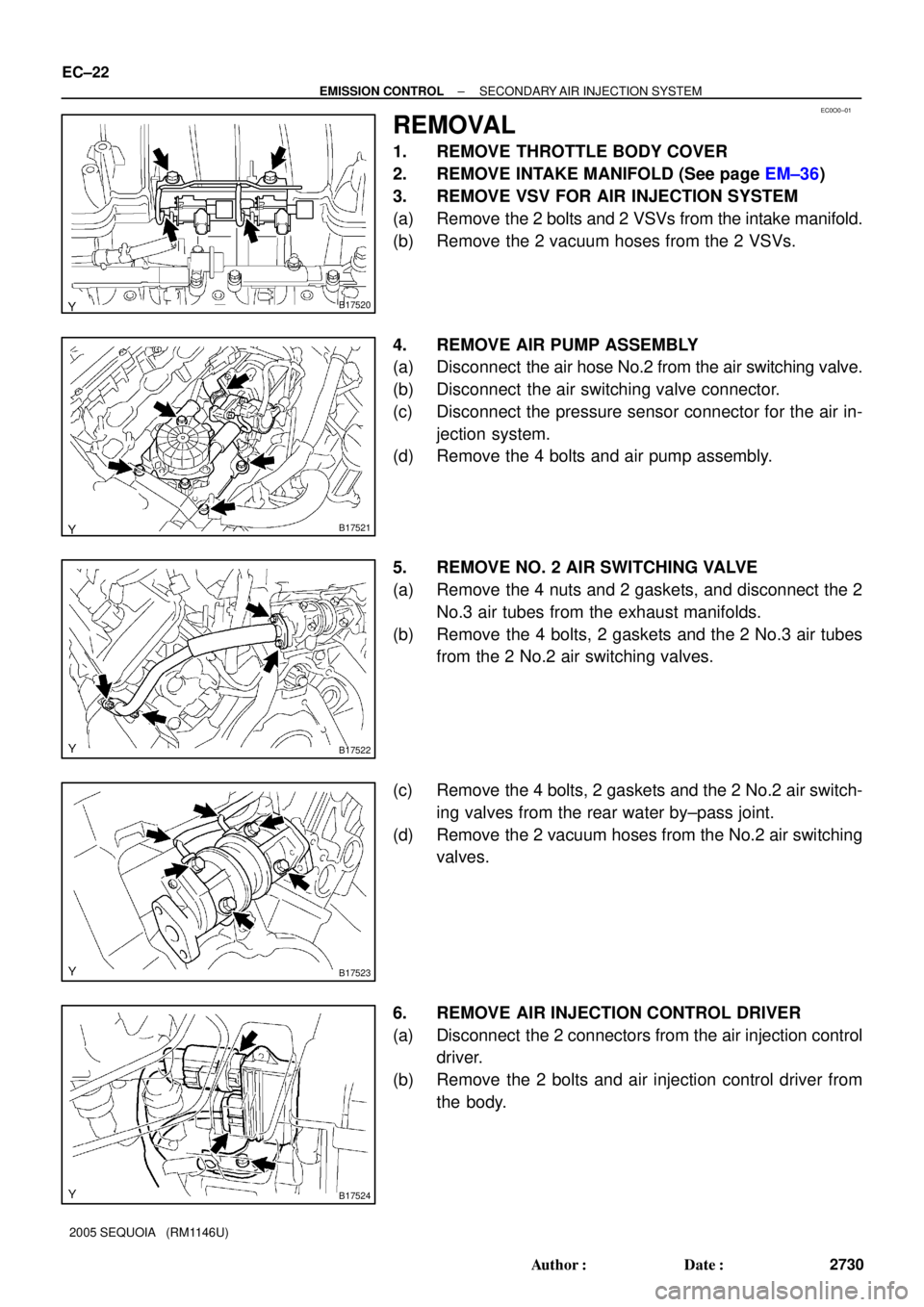
3. REMOVE VSV FOR AIR INJECTION SYSTEM
(a) Remove the 2 bolts and 2 VSVs from the intake manifold.
(b) Remove the 2 vacuum hoses from the 2 VSVs.
4. REMOVE AIR PUMP ASSEMBLY
(a) Disconnect the air hose No.2 from the air switching valve.
(b) Disconnect the air switching valve connector.
(c) Disconnect the pressure sensor connector for the air in-
jection system.
(d) Remove the 4 bolts and air pump assembly.
5. REMOVE NO. 2 AIR SWITCHING VALVE
(a) Remove the 4 nuts and 2 gaskets, and disconnect the 2
No.3 air tubes from the exhaust manifolds.
(b) Remove the 4 bolts, 2 gaskets and the 2 No.3 air tubes
from the 2 No.2 air switching valves.
(c) Remove the 4 bolts, 2 gaskets and the 2 No.2 air switch-
ing valves from the rear water by±pass joint.
(d) Remove the 2 vacuum hoses from the No.2 air switching
valves.
6. REMOVE AIR INJECTION CONTROL DRIVER
(a) Disconnect the 2 connectors from the air injection control
driver.
(b) Remove the 2 bolts and air injection control driver from
the body.
Page 2742 of 4323

EC0O4±01
B17524
B17523
B17522
B17521
B17520
EC±26
± EMISSION CONTROLSECONDARY AIR INJECTION SYSTEM
2734 Author�: Date�:
2005 SEQUOIA (RM1146U)
INSTALLATION
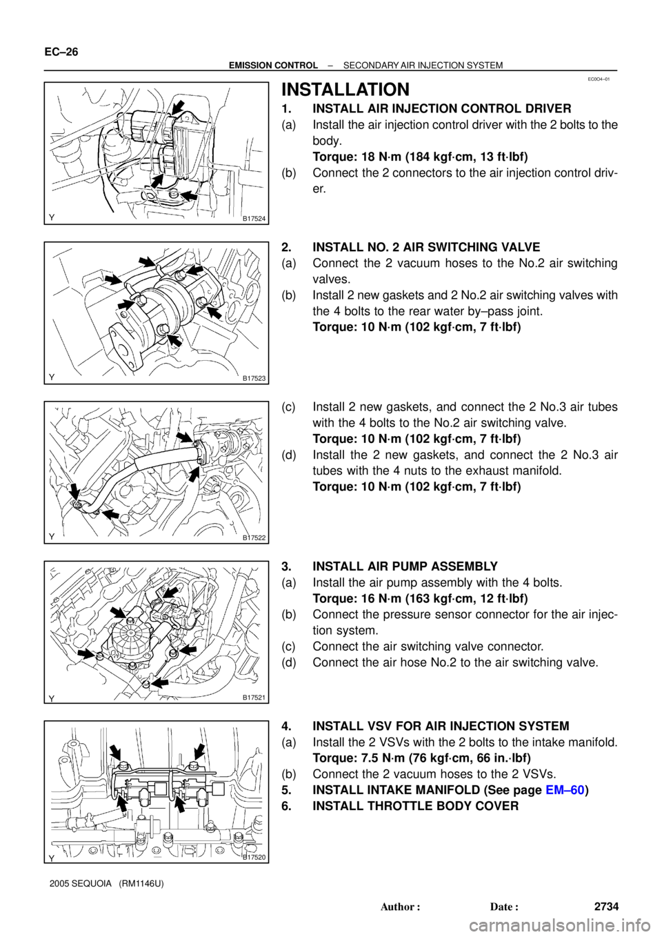
1. INSTALL AIR INJECTION CONTROL DRIVER
(a) Install the air injection control driver with the 2 bolts to the
body.
Torque: 18 N´m (184 kgf´cm, 13 ft´lbf)
(b) Connect the 2 connectors to the air injection control driv-
er.
2. INSTALL NO. 2 AIR SWITCHING VALVE
(a) Connect the 2 vacuum hoses to the No.2 air switching
valves.
(b) Install 2 new gaskets and 2 No.2 air switching valves with
the 4 bolts to the rear water by±pass joint.
Torque: 10 N´m (102 kgf´cm, 7 ft´lbf)
(c) Install 2 new gaskets, and connect the 2 No.3 air tubes
with the 4 bolts to the No.2 air switching valve.
Torque: 10 N´m (102 kgf´cm, 7 ft´lbf)
(d) Install the 2 new gaskets, and connect the 2 No.3 air
tubes with the 4 nuts to the exhaust manifold.
Torque: 10 N´m (102 kgf´cm, 7 ft´lbf)
3. INSTALL AIR PUMP ASSEMBLY
(a) Install the air pump assembly with the 4 bolts.
Torque: 16 N´m (163 kgf´cm, 12 ft´lbf)
(b) Connect the pressure sensor connector for the air injec-
tion system.
(c) Connect the air switching valve connector.
(d) Connect the air hose No.2 to the air switching valve.
4. INSTALL VSV FOR AIR INJECTION SYSTEM
(a) Install the 2 VSVs with the 2 bolts to the intake manifold.
Torque: 7.5 N´m (76 kgf´cm, 66 in.´lbf)
(b) Connect the 2 vacuum hoses to the 2 VSVs.
5. INSTALL INTAKE MANIFOLD (See page EM±60)
6. INSTALL THROTTLE BODY COVER
Page 2744 of 4323

FI2553
SST
B16498
New Gasket
SF±2
± SFISFI SYSTEM
2736 Author�: Date�:
2005 SEQUOIA (RM1146U)
(b) When installing the battery, be especially careful to cor-
rectly connect the positive (+) and negative (±) cables.
(c) Do not give a severe impact to the SFI parts during remov-
al or installation. Handle all SFI parts carefully, especially
the ECM.
(d) Be careful during troubleshooting. Numerous transistor
circuits are used and even slight terminal contact can
cause further trouble.
(e) Do not open the ECM cover.
(f) When inspecting during rainy weather, take care to pre-
vent entry of water. Also, when washing the engine
compartment, prevent water from getting into the SFI
parts and wiring connectors.
(g) Parts should be replaced as an assembly.
(h) Care should be taken when pulling out and inserting wir-
ing connectors.
(1) Release the lock and pull out the connector, pulling
on the connectors.
(2) Fully insert the connector and check that it is locked.
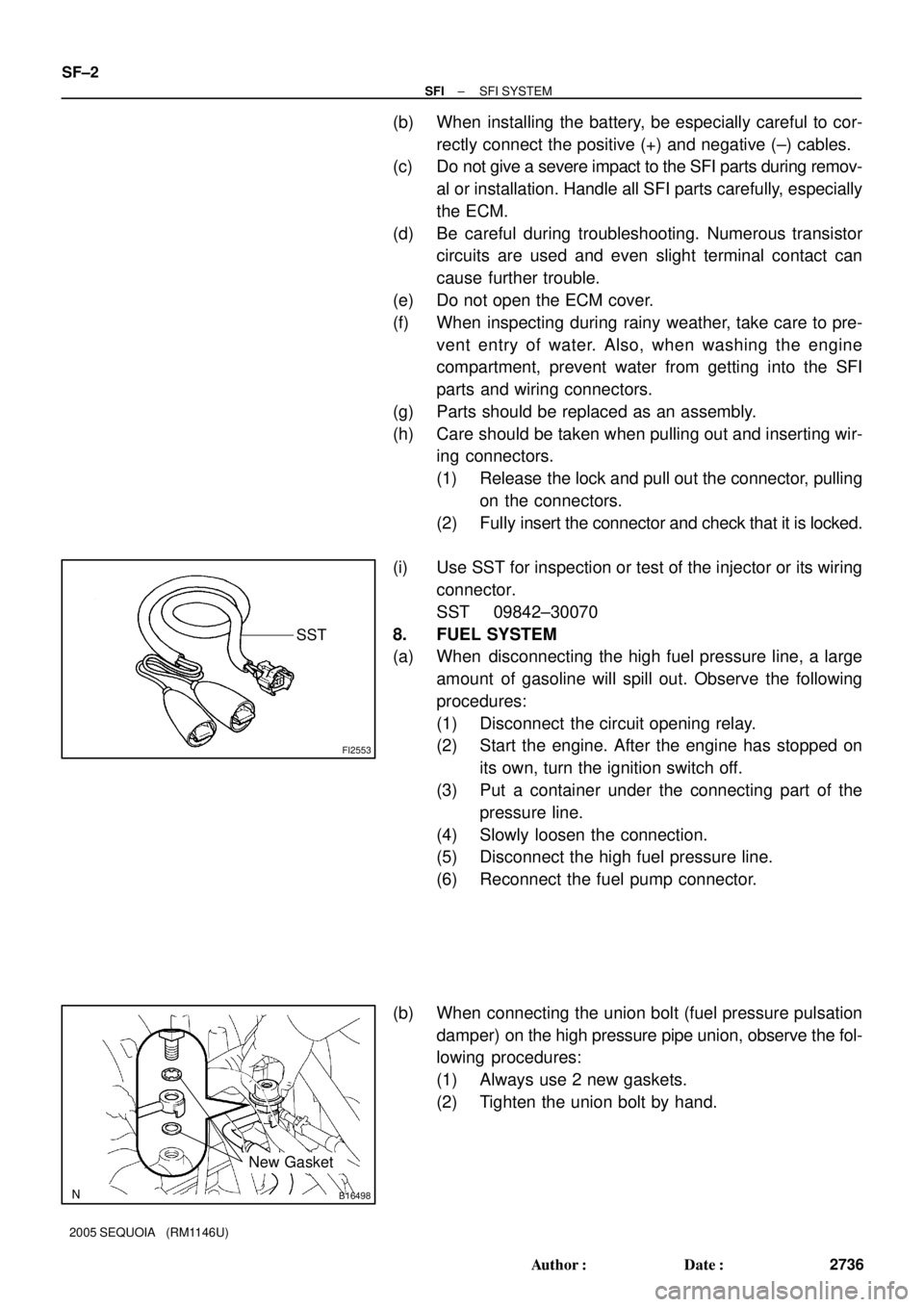
(i) Use SST for inspection or test of the injector or its wiring
connector.
SST 09842±30070
8. FUEL SYSTEM
(a) When disconnecting the high fuel pressure line, a large
amount of gasoline will spill out. Observe the following
procedures:
(1) Disconnect the circuit opening relay.
(2) Start the engine. After the engine has stopped on
its own, turn the ignition switch off.
(3) Put a container under the connecting part of the
pressure line.
(4) Slowly loosen the connection.
(5) Disconnect the high fuel pressure line.
(6) Reconnect the fuel pump connector.
(b) When connecting the union bolt (fuel pressure pulsation
damper) on the high pressure pipe union, observe the fol-
lowing procedures:
(1) Always use 2 new gaskets.
(2) Tighten the union bolt by hand.
Page 2827 of 4323
CO0IQ±10
D12721
Intake Air
Connector PS Air
Hose
No.2 Fan ShroudThrottle Body Cover
Fan Pulley
Drive Belt Fan with Fluid Coupling
A/C Compressor
A/C Compressor
Connector
Engine Under Cover (4WD) x 5Radiator Assembly
N´m (kgf´cm, ft´lbf): Specified torque
12 (120, 9)
49 (500, 36)
A/T Oil Cooler Hose
Clip
Clip
Engine Under Cover (2WD) Vacuum Hose
PCV Hose
Suction Hose
MAF Meter Wire
± COOLINGWATER PUMP
CO±3
2819 Author�: Date�:
2005 SEQUOIA (RM1146U)
WATER PUMP
COMPONENTS
Page 2828 of 4323
B17476
RH No.3 Timing Belt Cover
LH No.3 Timing Belt CoverNo.2 Timing Belt Cover
Camshaft Position
Sensor Connector
Engine Wire
Oil Cooler Pipe
Timing Belt
Fan Bracket Drive Belt Timing Pulley
Timing Belt Tensioner Dust Boot
N´m (kgf´cm, ft´lbf) : Specified torque Cover Plate
39 (400,29)
32 (330, 24)
16 (160, 12)
Water Bypass
Hose
Grommet
16 (160, 12)
245 (2,500, 181)
CO±4
± COOLINGWATER PUMP
2820 Author�: Date�:
2005 SEQUOIA (RM1146U)
Page 2829 of 4323
B17477
Generator Wire
Generator Connector
Generator
Crankshaft PulleyDrive Belt Tensioner
No.1 Timing Belt Cover
Timing Belt
Timing Belt Guide
(Crankshaft Angle Sensor Plate)No.2 Idler Pulley
Timing Belt Cover SpacerGasket
N´m (kgf´cm, ft´lbf) : Specified torque
� Non±reusable partWater Inlet Housing
Assembly
Water Pump � O±Ring
� Gasket � O±Ring
39 (400, 29)
18 (185, 13)
21 (215, 15)
Wire
Clamp
PS Vane Pump
(100 A Type Generator)
15.5 (158, 11)
39 (400, 29)
34.5 (350, 25)
± COOLINGWATER PUMP
CO±5
2821 Author�: Date�:
2005 SEQUOIA (RM1146U)
Page 2830 of 4323
CO0IR±06
B17478
B17479
CO±6
± COOLINGWATER PUMP
2822 Author�: Date�:
2005 SEQUOIA (RM1146U)
REMOVAL
1. DRAIN ENGINE COOLANT
2. REMOVE TIMING BELT (See page EM±16)
3. REMOVE NO.2 IDLER PULLEY (See page EM±16)
4. REMOVE WATER INLET AND INLET HOUSING AS-
SEMBLY
(a) Disconnect the water bypass hose from the water inlet
housing.
(b) Remove the 2 bolts holding the water inlet housing to the
water pump.
(c) Disconnect the water inlet housing from the front water
bypass joint, and remove the water inlet and inlet housing
assembly.
(d) Remove the O±ring from the water inlet housing.
5. REMOVE WATER PUMP
(a) Remove the 5 bolts, 2 stud bolts, nut, water pump and
gasket.
(b) Remove the O±ring from the water bypass pipe.