Page 3253 of 4323

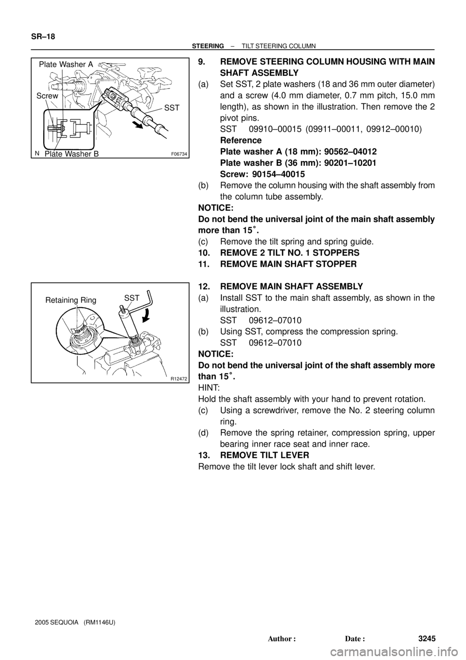
F06734
Plate Washer A
Plate Washer BSST
Screw
R12472
SST
Retaining Ring SR±18
± STEERINGTILT STEERING COLUMN
3245 Author�: Date�:
2005 SEQUOIA (RM1146U)
9. REMOVE STEERING COLUMN HOUSING WITH MAIN
SHAFT ASSEMBLY
(a) Set SST, 2 plate washers (18 and 36 mm outer diameter)
and a screw (4.0 mm diameter, 0.7 mm pitch, 15.0 mm
length), as shown in the illustration. Then remove the 2
pivot pins.
SST 09910±00015 (09911±00011, 09912±00010)
Reference
Plate washer A (18 mm): 90562±04012
Plate washer B (36 mm): 90201±10201
Screw: 90154±40015
(b) Remove the column housing with the shaft assembly from
the column tube assembly.
NOTICE:
Do not bend the universal joint of the main shaft assembly
more than 15°.
(c) Remove the tilt spring and spring guide.
10. REMOVE 2 TILT NO. 1 STOPPERS
11. REMOVE MAIN SHAFT STOPPER
12. REMOVE MAIN SHAFT ASSEMBLY
(a) Install SST to the main shaft assembly, as shown in the
illustration.
SST 09612±07010
(b) Using SST, compress the compression spring.
SST 09612±07010
NOTICE:
Do not bend the universal joint of the shaft assembly more
than 15°.
HINT:
Hold the shaft assembly with your hand to prevent rotation.
(c) Using a screwdriver, remove the No. 2 steering column
ring.
(d) Remove the spring retainer, compression spring, upper
bearing inner race seat and inner race.
13. REMOVE TILT LEVER
Remove the tilt lever lock shaft and shift lever.
Page 3256 of 4323

SR0V3±05
R12807
Washer
Retaining RingSST
F06735
F06736
± STEERINGTILT STEERING COLUMN
SR±21
3248 Author�: Date�:
2005 SEQUOIA (RM1146U)
REASSEMBLY
NOTICE:
When using a vise, do not overtighten it.
1. COAT PARTS INDICATED BY ARROWS WITH MOLYB-
DENUM DISULFIDE LITHIUM BASE GREASE (See
page SR±12)
2. INSTALL TILT LEVER
Install the tilt lever with a new tilt lever lock shaft.
Torque: 9.0 N´m (90 kgf´cm, 78 in.´lbf)
3. INSTALL MAIN SHAFT ASSEMBLY
(a) Install the inner race, upper bearing inner race seat, com-
pression spring and spring retainer.
(b) Install a new No. 2 steering column ring to the main shaft
assembly.
(c) Install the washer of SST on the main shaft assembly.
SST 09612±07010
(d) Set SST on the main shaft assembly, as shown in the il-
lustration.
SST 09612±07010
(e) Using SST, push down the retaining ring until it fits into the
shaft groove and install the main shaft assembly.
NOTICE:
Do not bend the universal joint of the shaft assembly more
than 15°.
HINT:
Hold the main shaft assembly with your hand to prevent rota-
tion.
4. INSTALL MAIN SHAFT STOPPER
5. INSTALL 2 NEW TILT NO. 1 STOPPERS
6. INSTALL STEERING COLUMN HOUSING WITH MAIN
SHAFT ASSEMBLY
(a) Install the steering column housing with the main shaft as-
sembly into the column tube assembly.
(b) Install the tilt spring and spring guide.
(c) Hold the steering column housing and steering column
housing support in a vise.
(d) Temporarily install 2 new pivot pins.
(e) Using a punch and a hammer, tap in the pivot pin.
(f) Using a pin punch and a hammer, stake at 3 places evenly
around the hole as shown in the illustration.
Page 3734 of 4323
BO47V±04
H16752
Center Leg Cover
Front Leg
Front Leg CushionNo. 1 Roof Inner Rack
Bracket Center SupportRoof Inner Rack Retainer
Weatherstrip
Front Leg Cover
Front Leg
Front Leg Cushion Front Leg CoverRear Leg CoverFront StayRoof Rack Bar Joint
Center Support
Sub±assemblyRoof Inner
Rack Retainer
Rear Leg Cover
Rear Leg
Rear Leg Cover
Center Leg Cover
Rear Leg
Rear Leg Cushion
11 (115, 8)
N´m (kgf´cm, ft´lbf) : Specified torque
11 (115, 8)
11 (115, 8)
11 (115, 8)
11 (115, 8)
11 (115, 8)
± BODYROOF RACK
BO±173
3726 Author�: Date�:
2005 SEQUOIA (RM1146U)
ROOF RACK
COMPONENTS