Page 2831 of 4323
CO0UZ±05
B04067Air HoleWa t e r
Hole
P21661
P21660
B07456
± COOLINGWATER PUMP
CO±7
2823 Author�: Date�:
2005 SEQUOIA (RM1146U)
INSPECTION
1. INSPECT WATER PUMP
(a) Visually check the air hole and water hole for coolant leak-
age.
If leakage is found, replace the water pump and timing belt.
(b) Turn the pulley, and check that the water pump bearing
moves smoothly and quietly.
If necessary, replace the water pump.
2. INSPECT FLUID COUPLING
(a) Remove the 4 nuts and fan from the fluid coupling.
(b) Check that the fluid coupling is not damaged and that no
silicon oil leaks.
If necessary, replace the fluid coupling.
(c) Reinstall the fan to the fluid coupling with the 4 nuts.
Torque: 8.5 N´m (85 kgf´cm, 75 in.´lbf)
3. INSPECT FAN PULLEY BRACKET
Check the turning smoothness of the fan pulley.
If necessary, replace the pulley bracket.
4. INSPECT TIMING BELT COMPONENTS
(See page EM±21)
Page 2832 of 4323

CO0IT±06
B04463
Connect
New O±Ring
B03030
Seal Width
2 ± 3 mm
New O±Ring
CO±8
± COOLINGWATER PUMP
2824 Author�: Date�:
2005 SEQUOIA (RM1146U)
INSTALLATION
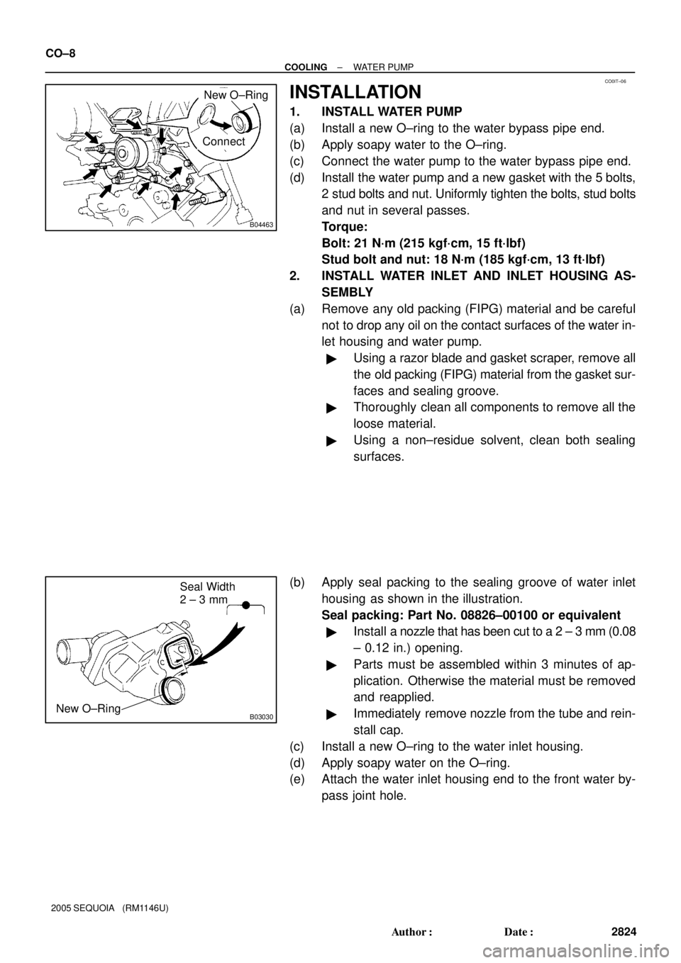
1. INSTALL WATER PUMP
(a) Install a new O±ring to the water bypass pipe end.
(b) Apply soapy water to the O±ring.
(c) Connect the water pump to the water bypass pipe end.
(d) Install the water pump and a new gasket with the 5 bolts,
2 stud bolts and nut. Uniformly tighten the bolts, stud bolts
and nut in several passes.
Torque:
Bolt: 21 N´m (215 kgf´cm, 15 ft´lbf)
Stud bolt and nut: 18 N´m (185 kgf´cm, 13 ft´lbf)
2. INSTALL WATER INLET AND INLET HOUSING AS-
SEMBLY
(a) Remove any old packing (FIPG) material and be careful
not to drop any oil on the contact surfaces of the water in-
let housing and water pump.
�Using a razor blade and gasket scraper, remove all
the old packing (FIPG) material from the gasket sur-
faces and sealing groove.
�Thoroughly clean all components to remove all the
loose material.
�Using a non±residue solvent, clean both sealing
surfaces.
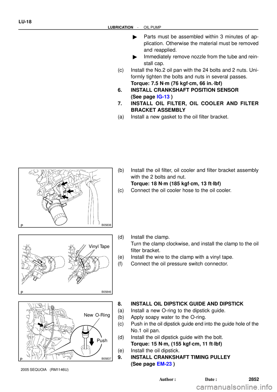
(b) Apply seal packing to the sealing groove of water inlet
housing as shown in the illustration.
Seal packing: Part No. 08826±00100 or equivalent
�Install a nozzle that has been cut to a 2 ± 3 mm (0.08
± 0.12 in.) opening.
�Parts must be assembled within 3 minutes of ap-
plication. Otherwise the material must be removed
and reapplied.
�Immediately remove nozzle from the tube and rein-
stall cap.
(c) Install a new O±ring to the water inlet housing.
(d) Apply soapy water on the O±ring.
(e) Attach the water inlet housing end to the front water by-
pass joint hole.
Page 2833 of 4323
B17478
AB
± COOLINGWATER PUMP
CO±9
2825 Author�: Date�:
2005 SEQUOIA (RM1146U)
(f) Install the water inlet and housing assembly with the 2
bolts. Alternately tighten the bolts.
Torque: 18 N´m (185 kgf´cm, 13 ft´lbf)
HINT:
Each bolt length is indicated in the illustration.
Bolt length:
76 mm (3.00 in.) for A
22 mm (0.87 in.) for B
(g) Connect the water bypass hose to the water inlet housing.
3. INSTALL NO.2 IDLER PULLEY (See page EM±23)
4. INSTALL TIMING BELT (See page EM±23)
5. FILL WITH ENGINE COOLANT
6. START ENGINE AND CHECK FOR ENGINE COOLANT
LEAKS
7. RECHECK ENGINE COOLANT LEVEL
Page 2839 of 4323

CO0IZ±08
CO1242
Radiator Cap Tester
Radiator Cap
30° or More
B07240
Radiator Cap Tester
± COOLINGRADIATOR
CO±15
2831 Author�: Date�:
2005 SEQUOIA (RM1146U)
ON±VEHICLE INSPECTION
1. REMOVE RADIATOR CAP
CAUTION:
To avoid the danger of being burned, do not remove the ra-
diator cap while the engine and radiator are still hot, as fluid
and steam can be blown out under pressure.
2. INSPECT RADIATOR CAP
NOTICE:
�If the radiator cap has contaminations, always rinse
it with water.
�Before using a radiator cap tester, wet the relief valve
and pressure valve with engine coolant or water.
�When performing steps (a) and (b) below, keep the
tester at an angle of over 30° above the horizontal.
(a) Using a radiator cap tester, slowly pump the tester and
check that air is coming from the vacuum valve.
Pump speed: 1 push/(3 seconds or more)
NOTICE:
Push the pump at a constant speed.
If air is not coming from the vacuum valve, replace the radiator
cap.
(b) Pump the radiator cap tester, and measure the relief valve
opening pressure.
Pump speed: 1 push within 1 second
NOTICE:
This pump speed is for the first pump only (in order to close
the vacuum valve). After this, the pump speed can be re-
duced.
Opening pressure:
Standard74 to 103 kPa (0.75 to 1.05 kgf/cm2,10.7 to 14.9 psi)
Minimum59 kPa (0.6 kgf/cm2, 8.6 psi)
HINT:
Use the tester's maximum reading as the opening pressure.
If the opening pressure is less than minimum, replace the radia-
tor cap.
3. INSPECT COOLING SYSTEM FOR LEAKS
(a) Fill the radiator with coolant and attach a radiator cap tes-
ter.
(b) Warm up the engine.
(c) Pump it to 118 kPa (1.2 kgf/cm
2, 17.1 psi), and check that
the pressure does not drop.
If the pressure drops, check the hoses, radiator or water pump
for leaks. If no external leaks are found, check the heater core,
cylinder block and head.
4. REINSTALL RADIATOR CAP
Page 2846 of 4323
LU08P±10
B17476
RH No.3 Timing Belt Cover
LH No.3 Timing Belt CoverNo.2 Timing Belt Cover
Camshaft Position
Sensor Connector
Engine Wire
Drive Belt Idler PulleyTiming Belt
Fan Bracket
N´m (kgf´cm, ft´lbf) : Specified torqueOil Cooler Pipe
Timing Belt Tensioner Dust Boot
Cover Plate
32 (330, 24)
Water Bypass
Hose
Grommet
245 (2,500, 181)
39 (400,29)
16 (160, 12)
16 (160, 12)
LU±4
± LUBRICATIONOIL PUMP
2838 Author�: Date�:
2005 SEQUOIA (RM1146U)
OIL PUMP
COMPONENTS
Page 2860 of 4323

B05838
B05846
Vinyl Tape
B05837
Push New O-Ring
LU-18
- LUBRICATIONOIL PUMP
2852 Author�: Date�:
2005 SEQUOIA (RM1146U)
�Parts must be assembled within 3 minutes of ap-
plication. Otherwise the material must be removed
and reapplied.
�Immediately remove nozzle from the tube and rein-
stall cap.
(c) Install the No.2 oil pan with the 24 bolts and 2 nuts. Uni-
formly tighten the bolts and nuts in several passes.
Torque: 7.5 N´m (76 kgf´cm, 66 in.´lbf)
6. INSTALL CRANKSHAFT POSITION SENSOR
(See page IG-13)
7. INSTALL OIL FILTER, OIL COOLER AND FILTER
BRACKET ASSEMBLY
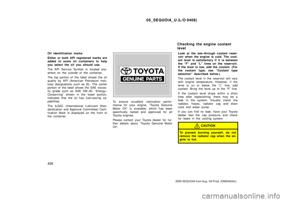
(a) Install a new gasket to the oil filter bracket.
(b) Install the oil filter, oil cooler and filter bracket assembly
with the 2 bolts and nut.
Torque: 18 N´m (185 kgf´cm, 13 ft´lbf)
(c) Connect the oil cooler hose to the oil cooler.
(d) Install the clamp.
Turn the clamp clockwise, and install the clamp to the oil
filter bracket.
(e) Install the wire to the clamp with a vinyl tape.
(f) Connect the oil pressure switch connector.
8. INSTALL OIL DIPSTICK GUIDE AND DIPSTICK
(a) Install a new O-ring to the dipstick guide.
(b) Apply soapy water to the O-ring.
(c) Push in the oil dipstick guide end into the guide hole of the
No.1 oil pan.
(d) Install the oil dipstick guide with the bolt.
Torque: 15 N´m, (155 kgf´cm, 11 ft´lbf)
(e) Install the oil dipstick.
9. INSTALL CRANKSHAFT TIMING PULLEY
(See page EM-23)
Page 4285 of 4323

05_SEQUOIA_U (L/O 0408)
426
2005 SEQUOIA from Aug. '04 Prod. (OM34424U)
Oil identification marks
Either or both API registered marks are
added to some oil containers to help
you select the oil you should use.
The API Service Symbol is located any-
where on the outside of the container.
The top portion of the label shows the oil
quality by API (American Petroleum Insti-
tute) designations such as SL. The center
portion of the label shows the SAE viscos-
ity grade such as SAE 5W±30. ªEnergy±
Conservingº shown in the lower portion,
indicates that the oil has fuel±saving ca-
pabilities.
The ILSAC (International Lubricant Stan-
dardization and Approval Committee) Certi-
fication Mark is displayed on the front of
the container.
To ensure excellent lubrication perfor-
mance for your engine, ªToyota Genuine
Motor Oilº is available, which has been
specifically tested and approved for all
Toyota engines.
Please contact your Toyota dealer for fur-
ther details about ªToyota Genuine Motor
Oilº.Look at the see±through coolant reser-
voir when the engine is cold. The cool-
ant level is satisfactory if it is between
the ªFº and ªLº lines on the reservoir.
If the level is low, add the coolant. (For
the coolant type, see ªCoolant type
selectionº described below.)
The coolant level in the reservoir will vary
with engine temperature. However, if the
level is on or below the ªLº line, add
coolant. Bring the level up to the ªFº line.
If the coolant level drops within a short
time after replenishing, there may be a
leak in the system. Visually check the
radiator, hoses, radiator cap and drain
cock and water pump.
If you can find no leak, have your Toyota
dealer test the cap pressure and check
for leaks in the cooling system.
CAUTION
To prevent burning yourself, do not
remove the radiator cap when the en-
gine is hot.
Checking the engine coolant
level
Page 4290 of 4323

05_SEQUOIA_U (L/O 0408)
431
2005 SEQUOIA from Aug. '04 Prod. (OM34424U)
5. After completing the tire inflation
pressure measurement and ad-
justment, apply soapy water to the
valve and check for leakage.
6. Install the tire valve cap.
If a gauge and air pump are not avail-
able, have your vehicle checked by
your Toyota dealer.
CAUTION
Be sure to reinstall the tire valve
caps. Without the valve caps, dirt
or moisture could get into the
valve core and cause air leakage.
If the caps have been lost, have
new ones put on as soon as pos-
sible.
Incorrect tire inflation pressure may
waste fuel, reduce the comfort of driv-
ing, reduce tire life and make your ve-
hicle less safe to drive.
If a tire frequently needs refilling,
have it checked by your Toyota deal-
er.
CAUTION
Keep your tires properly inflated.
Otherwise, the following condi-
tions may occur and cause an ac-
cident resulting in death or seri-
ous injuries.
Low tire pressure (underinfla-
tion)Ð
�Excessive wear
�Uneven wear
�Poor handling
�Possibility of blowouts from an
overheated tire
�Poor sealing of the tire bead
�Wheel deformation and/or tire
separation
�A greater possibility of tire
damage from road hazards
High tire pressure (overinfla-
tion)Ð
�Poor handling
�Excessive wear
�Uneven wear
�A greater possibility of tire
damage from road hazards