Page 2609 of 4323
P20634
P20635
Protrusion EM±22
± ENGINE MECHANICALTIMING BELT
2601 Author�: Date�:
2005 SEQUOIA (RM1146U)
(b) Hold the tensioner with both hands and push the push rod
strongly as shown to check that it doesn't move.
If the push rod moves, replace the tensioner.
NOTICE:
Never hold the tensioner push rod facing downward.
(c) Measure the protrusion of the push rod from the housing
end.
Protrusion: 10.5 to 11.5 mm (0.413 to 0.453 in.)
If the protrusion is not as specified, replace the tensioner.
4. INSPECT WATER PUMP (See page CO±7)
Page 2610 of 4323
EM1WY±01
A04446
SST
Inward
A04447
A04342
± ENGINE MECHANICALTIMING BELT
EM±23
2602 Author�: Date�:
2005 SEQUOIA (RM1146U)
INSTALLATION
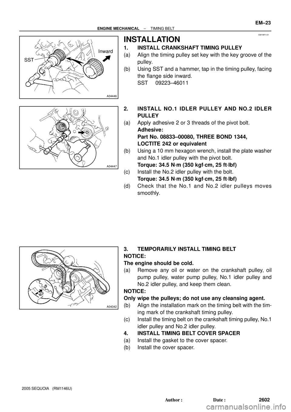
1. INSTALL CRANKSHAFT TIMING PULLEY
(a) Align the timing pulley set key with the key groove of the
pulley.
(b) Using SST and a hammer, tap in the timing pulley, facing
the flange side inward.
SST 09223±46011
2. INSTALL NO.1 IDLER PULLEY AND NO.2 IDLER
PULLEY
(a) Apply adhesive 2 or 3 threads of the pivot bolt.
Adhesive:
Part No. 08833±00080, THREE BOND 1344,
LOCTITE 242 or equivalent
(b) Using a 10 mm hexagon wrench, install the plate washer
and No.1 idler pulley with the pivot bolt.
Torque: 34.5 N´m (350 kgf´cm, 25 ft´lbf)
(c) Install the No.2 idler pulley with the bolt.
Torque: 34.5 N´m (350 kgf´cm, 25 ft´lbf)
(d) Check that the No.1 and No.2 idler pulleys moves
smoothly.
3. TEMPORARILY INSTALL TIMING BELT
NOTICE:
The engine should be cold.
(a) Remove any oil or water on the crankshaft pulley, oil
pump pulley, water pump pulley, No.1 idler pulley and
No.2 idler pulley, and keep them clean.
NOTICE:
Only wipe the pulleys; do not use any cleansing agent.
(b) Align the installation mark on the timing belt with the tim-
ing mark of the crankshaft timing pulley.
(c) Install the timing belt on the crankshaft timing pulley, No.1
idler pulley and No.2 idler pulley.
4. INSTALL TIMING BELT COVER SPACER
(a) Install the gasket to the cover spacer.
(b) Install the cover spacer.
Page 2612 of 4323
A23316
Hold
SST
A23317
Turn
SST
A23318
SST
Tension
Turn
A23319
SST
Turn
± ENGINE MECHANICALTIMING BELT
EM±25
2604 Author�: Date�:
2005 SEQUOIA (RM1146U)
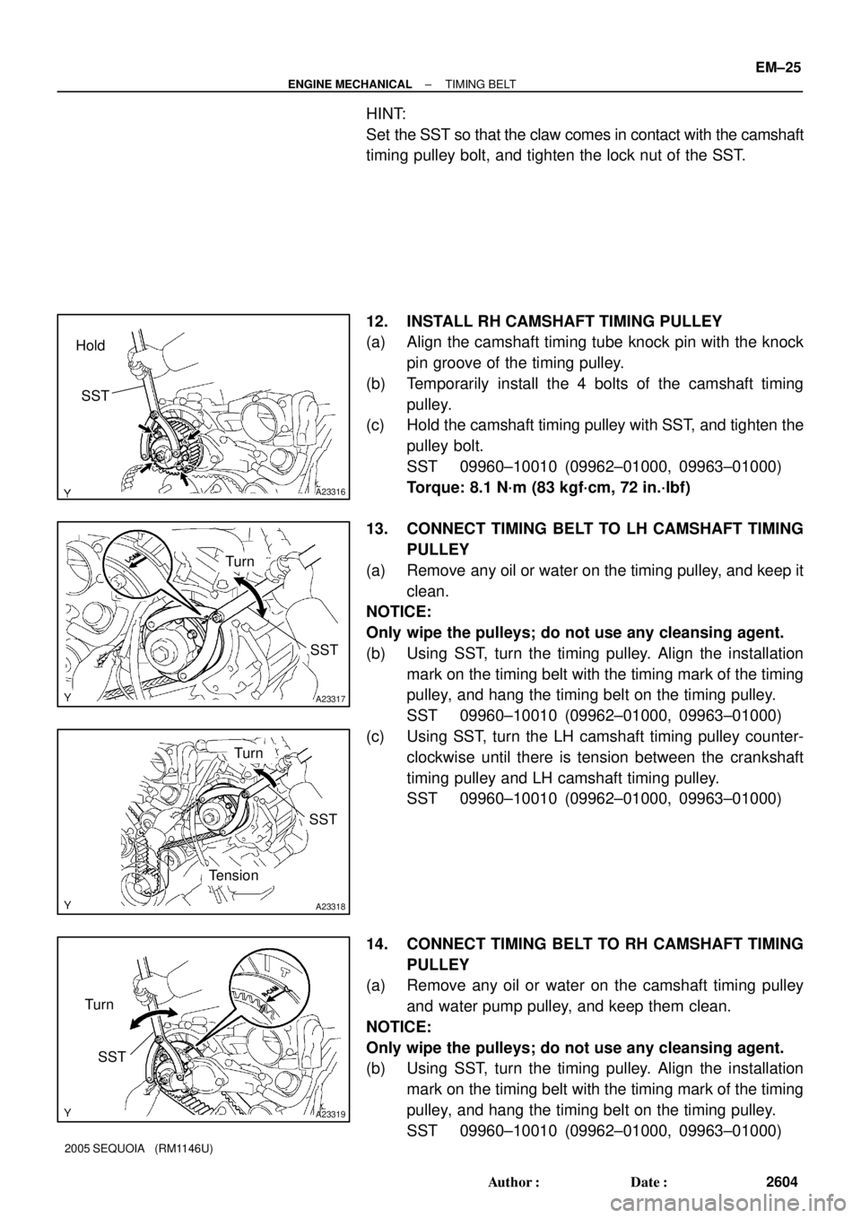
HINT:
Set the SST so that the claw comes in contact with the camshaft
timing pulley bolt, and tighten the lock nut of the SST.
12. INSTALL RH CAMSHAFT TIMING PULLEY
(a) Align the camshaft timing tube knock pin with the knock
pin groove of the timing pulley.
(b) Temporarily install the 4 bolts of the camshaft timing
pulley.
(c) Hold the camshaft timing pulley with SST, and tighten the
pulley bolt.
SST 09960±10010 (09962±01000, 09963±01000)
Torque: 8.1 N´m (83 kgf´cm, 72 in.´lbf)
13. CONNECT TIMING BELT TO LH CAMSHAFT TIMING
PULLEY
(a) Remove any oil or water on the timing pulley, and keep it
clean.
NOTICE:
Only wipe the pulleys; do not use any cleansing agent.
(b) Using SST, turn the timing pulley. Align the installation
mark on the timing belt with the timing mark of the timing
pulley, and hang the timing belt on the timing pulley.
SST 09960±10010 (09962±01000, 09963±01000)
(c) Using SST, turn the LH camshaft timing pulley counter-
clockwise until there is tension between the crankshaft
timing pulley and LH camshaft timing pulley.
SST 09960±10010 (09962±01000, 09963±01000)
14. CONNECT TIMING BELT TO RH CAMSHAFT TIMING
PULLEY
(a) Remove any oil or water on the camshaft timing pulley
and water pump pulley, and keep them clean.
NOTICE:
Only wipe the pulleys; do not use any cleansing agent.
(b) Using SST, turn the timing pulley. Align the installation
mark on the timing belt with the timing mark of the timing
pulley, and hang the timing belt on the timing pulley.
SST 09960±10010 (09962±01000, 09963±01000)
Page 2619 of 4323
A23320
Rear Water
Bypass JointEngine Wire Protector
� Gasket
Injection Connector
Ignition Coil Connector
Ignition Coil Throttle Control
Connector
ECT
Sensor Connector
Front Water
Bypass Joint
Water Inlet and Inlet
Housing Assembly
Water Bypass Hose
LH No.1 Timing Belt Rear Plate
� Non±reusable partEngine Wire
� Gasket
� O±Ring
Engine WireHeater Hose
Throttle Body
Cover Bracket
VSV Connector
for EVAP Fuel Return Hose
Engine Wire
EVAP Hose
Heater Hose
Wire BracketFuel Inlet Hose
� Gasket
RH No.1 Timing Belt Rear Plate
� GasketAir Switching Valve No.2
Air Tube No.3
Air Tube No.3
� Gasket
N´m (kgf´cm, ft´lbf) : Specified torque� Gasket
18 (185, 13)
18 (185, 13)
18 (185, 13)
7.5 (76, 66 in.´lbf)
7.5 (76, 66 in.´lbf)
� Gasket
� Gasket
7.5 (76, 66 in.´lbf)
Air Pump Assembly
16 (163, 12)
10 (102, 7)
10 (102, 7)
16 (163, 12)
EM±32
± ENGINE MECHANICALCYLINDER HEAD
2611 Author�: Date�:
2005 SEQUOIA (RM1146U)
Page 2626 of 4323
A23332
Front Water Bypass Joint
A23333
Rear Water Bypass Joint
A05564
± ENGINE MECHANICALCYLINDER HEAD
EM±39
2618 Author�: Date�:
2005 SEQUOIA (RM1146U)
16. REMOVE WATER INLET AND INLET HOUSING AS-
SEMBLY (See page CO±6)
17. REMOVE AIR PUMP ASSEMBLY (See page EC±22)
18. REMOVE NO.2 AIR SWITCHING VALVES
(See page EC±22)
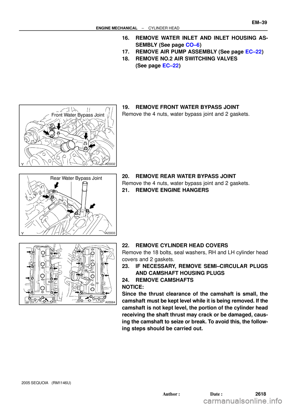
19. REMOVE FRONT WATER BYPASS JOINT
Remove the 4 nuts, water bypass joint and 2 gaskets.
20. REMOVE REAR WATER BYPASS JOINT
Remove the 4 nuts, water bypass joint and 2 gaskets.
21. REMOVE ENGINE HANGERS
22. REMOVE CYLINDER HEAD COVERS
Remove the 18 bolts, seal washers, RH and LH cylinder head
covers and 2 gaskets.
23. IF NECESSARY, REMOVE SEMI±CIRCULAR PLUGS
AND CAMSHAFT HOUSING PLUGS
24. REMOVE CAMSHAFTS
NOTICE:
Since the thrust clearance of the camshaft is small, the
camshaft must be kept level while it is being removed. If the
camshaft is not kept level, the portion of the cylinder head
receiving the shaft thrust may crack or be damaged, caus-
ing the camshaft to seize or break. To avoid this, the follow-
ing steps should be carried out.
Page 2658 of 4323
A04015
Wire
Clamp
Bracket
A23333
Rear Water Bypass Joint
A23332
Front Water Bypass Joint
A23331
± ENGINE MECHANICALCYLINDER HEAD
EM±71
2650 Author�: Date�:
2005 SEQUOIA (RM1146U)
(c) Install the gasket to the cylinder head cover.
(d) Install the seal washer to the bolt.
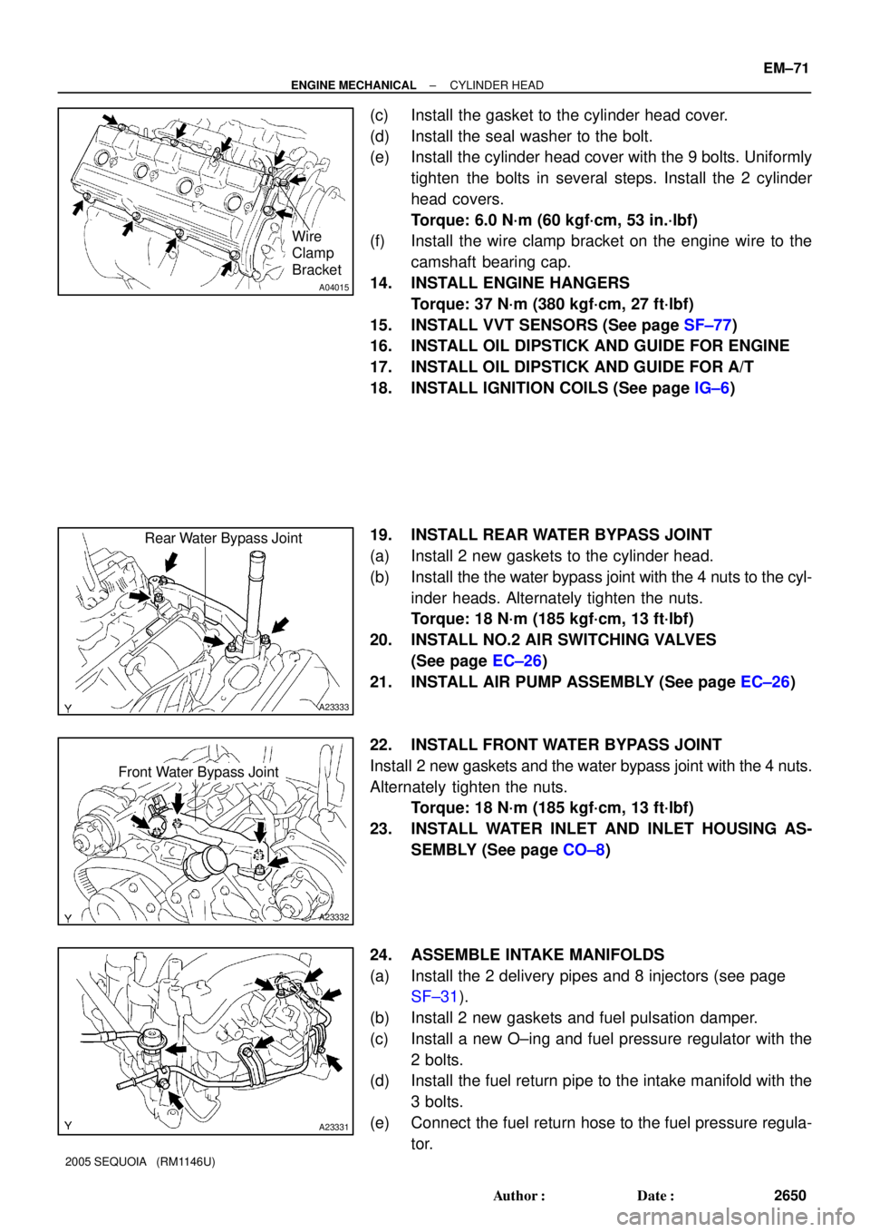
(e) Install the cylinder head cover with the 9 bolts. Uniformly
tighten the bolts in several steps. Install the 2 cylinder
head covers.
Torque: 6.0 N´m (60 kgf´cm, 53 in.´lbf)
(f) Install the wire clamp bracket on the engine wire to the
camshaft bearing cap.
14. INSTALL ENGINE HANGERS
Torque: 37 N´m (380 kgf´cm, 27 ft´lbf)
15. INSTALL VVT SENSORS (See page SF±77)
16. INSTALL OIL DIPSTICK AND GUIDE FOR ENGINE
17. INSTALL OIL DIPSTICK AND GUIDE FOR A/T
18. INSTALL IGNITION COILS (See page IG±6)
19. INSTALL REAR WATER BYPASS JOINT
(a) Install 2 new gaskets to the cylinder head.
(b) Install the the water bypass joint with the 4 nuts to the cyl-
inder heads. Alternately tighten the nuts.
Torque: 18 N´m (185 kgf´cm, 13 ft´lbf)
20. INSTALL NO.2 AIR SWITCHING VALVES
(See page EC±26)
21. INSTALL AIR PUMP ASSEMBLY (See page EC±26)
22. INSTALL FRONT WATER BYPASS JOINT
Install 2 new gaskets and the water bypass joint with the 4 nuts.
Alternately tighten the nuts.
Torque: 18 N´m (185 kgf´cm, 13 ft´lbf)
23. INSTALL WATER INLET AND INLET HOUSING AS-
SEMBLY (See page CO±8)
24. ASSEMBLE INTAKE MANIFOLDS
(a) Install the 2 delivery pipes and 8 injectors (see page
SF±31).
(b) Install 2 new gaskets and fuel pulsation damper.
(c) Install a new O±ing and fuel pressure regulator with the
2 bolts.
(d) Install the fuel return pipe to the intake manifold with the
3 bolts.
(e) Connect the fuel return hose to the fuel pressure regula-
tor.
Page 2686 of 4323
EM0E9±17
A23375
Engine Mounting Bracket
Oil Pump
Crankshaft
Front Oil
Seal
Crankshaft Position
Sensor Connector
No.1 Oil Pan
� Non±reusable part
� Precoated partOil StrainerEngine
Mounting
Bracket
VVT Sensor 2
ConnectorKnock Sensor 1
Knock Sensor 2
Engine Coolant
Drain UnionStarter
No.2 Oil Pan Oil Pan Baffle Platex 8 Water Pump
� Gasket � O±Ring
Engine
Wire
Engine
Wire
Cover VVT
Sensor 1
Engine Coolant
Drain Union
36 (370, 27)
30.5 (310, 22)
x 5
Oil Pressure
Sender Gauge
Connector
7.5 (76, 66 in.´lbf)
7.5 (76, 66 in.´lbf)
7.5 (76, 66 in.´lbf)
N´m (kgf´cm, ft´lbf) : Specified torque �
�
x 20
Clamp
Engine Wire Protector
� Tape
28 (290, 21)
7.5 (76, 66 in.´lbf)
28 (290, 21)
Water Bypass Pipe
7.5 (76, 66 in.´lbf)
� O±Ring
� Gasket
Engine
Wire
15.5 (160, 11)
39 (400, 29)
� Gasket
�
28 (290, 21)
7.5 (76, 66 in.´lbf)
x 4
± ENGINE MECHANICALCYLINDER BLOCK
EM±99
2678 Author�: Date�:
2005 SEQUOIA (RM1146U)
CYLINDER BLOCK
COMPONENTS
Page 2688 of 4323
EM122±05
A05112
Pull
Wire
Clamp
O±Ring
A08472
LH Side
± ENGINE MECHANICALCYLINDER BLOCK
EM±101
2680 Author�: Date�:
2005 SEQUOIA (RM1146U)
DISASSEMBLY
1. INSTALL ENGINE TO ENGINE STAND
2. REMOVE TIMING BELT AND PULLEYS
(See page EM±16)
3. REMOVE CYLINDER HEAD (See page EM±36)
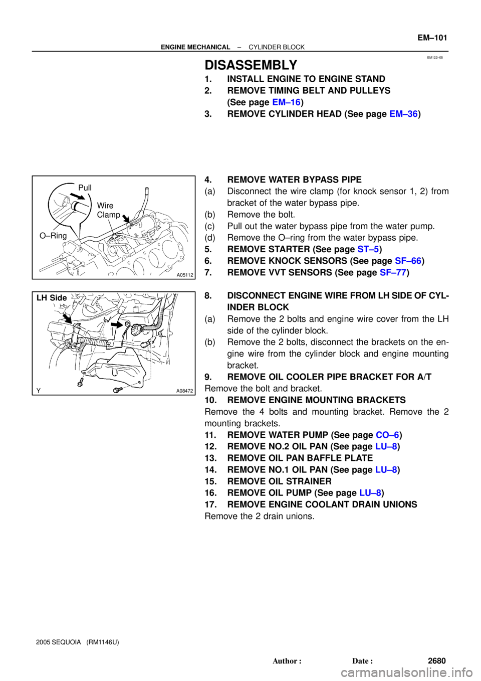
4. REMOVE WATER BYPASS PIPE
(a) Disconnect the wire clamp (for knock sensor 1, 2) from
bracket of the water bypass pipe.
(b) Remove the bolt.
(c) Pull out the water bypass pipe from the water pump.
(d) Remove the O±ring from the water bypass pipe.
5. REMOVE STARTER (See page ST±5)
6. REMOVE KNOCK SENSORS (See page SF±66)
7. REMOVE VVT SENSORS (See page SF±77)
8. DISCONNECT ENGINE WIRE FROM LH SIDE OF CYL-
INDER BLOCK
(a) Remove the 2 bolts and engine wire cover from the LH
side of the cylinder block.
(b) Remove the 2 bolts, disconnect the brackets on the en-
gine wire from the cylinder block and engine mounting
bracket.
9. REMOVE OIL COOLER PIPE BRACKET FOR A/T
Remove the bolt and bracket.
10. REMOVE ENGINE MOUNTING BRACKETS
Remove the 4 bolts and mounting bracket. Remove the 2
mounting brackets.
11. REMOVE WATER PUMP (See page CO±6)
12. REMOVE NO.2 OIL PAN (See page LU±8)
13. REMOVE OIL PAN BAFFLE PLATE
14. REMOVE NO.1 OIL PAN (See page LU±8)
15. REMOVE OIL STRAINER
16. REMOVE OIL PUMP (See page LU±8)
17. REMOVE ENGINE COOLANT DRAIN UNIONS
Remove the 2 drain unions.