Page 3791 of 4323
AC1L1±05
I21454
I21453
AC±56
± AIR CONDITIONINGCOMPRESSOR AND MAGNETIC CLUTCH
3783 Author�: Date�:
2005 SEQUOIA (RM1146U)
REMOVAL
1. RUN ENGINE AT IDLE SPEED WITH A/C ON FOR
APPROX. 10 MINUTES
2. STOP ENGINE
3. DISCONNECT CABLE FROM NEGATIVE BATTERY
TERMINAL
4. DISCHARGE REFRIGERANT FROM REFRIGERATION
SYSTEM
5. DISCONNECT DISCHARGE AND SUCTION HOSES
Remove the 2 nuts and disconnect both hoses.
NOTICE:
Cap the openings fitting immediately to keep moisture or
dirt out of the system.
6. REMOVE DRIVE BELT (See page AC±16)
7. REMOVE COMPRESSOR
(a) Disconnect the connector.
(b) Remove the 3 bolts and nut.
(c) Remove the cooler bracket.
(d) Remove the compressor.
Page 3795 of 4323
N04963
Dial Indicator
AC1L3±04
AC±60
± AIR CONDITIONINGCOMPRESSOR AND MAGNETIC CLUTCH
3787 Author�: Date�:
2005 SEQUOIA (RM1146U)
REASSEMBLY
Reassembly is in the reverse order of disassembly (See
page AC±57).
AFTER REASSEMBLY, CHECK MAGNETIC CLUTCH
CLEARANCE
(a) Set the dial indicator to the pressure plate of the magnetic
clutch.
(b) Connect the magnetic clutch lead wire to the positive (+)
terminal of the battery.
(c) Check the clearance between the pressure plate and ro-
tor when connecting the negative (±) terminal to the bat-
tery.
Standard clearance:
0.35 to 0.50 mm (0.014 to 0.024 in.)
If the clearance is not within the standard range, adjust the
clearance using shims to obtain the standard clearance.
Standard thickness:
0.1 mm (0.004 in.)
0.3 mm (0.012 in.)
0.5 mm (0.020in.)
Page 3796 of 4323

INSTALLATION
1. INSTALL COMPRESSOR
(a) Install the compressor with the cooler bracket w")
AC3HF±02
± AIR CONDITIONINGCOMPRESSOR AND MAGNETIC CLUTCH
AC±61
3788 Author�: Date�:
2005 SEQUOIA (RM1146U)
INSTALLATION
1. INSTALL COMPRESSOR
(a) Install the compressor with the cooler bracket with the 3 bolts and nut.
Torque:
Bolt: 47 N´m (480 kgf´cm, 35 in.´lbf)
Nut: 25 N´m (255 kgf´cm, 18 in.´lbf)
(b) Connect the connector.
2. CONNECT DISCHARGE AND SUCTION HOSES
Connect both hoses with the 2 nuts.
Torque: 10 N´m (100 kgf´cm, 7 in.´lbf)
NOTICE:
Hoses should be connected immediately after the caps have been removed.
HINT:
Lubricate 2 new O±rings with compressor oil and install them to the hoses.
3. INSTALL AND CHECK DRIVE BELT (See page AC±17, AC±15)
4. CONNECT CABLE TO NEGATIVE BATTERY TERMINAL
5. EVACUATE AIR FROM REFRIGERATION SYSTEM
6. CHARGE SYSTEM WITH REFRIGERANT
Specified amount:
Single A/C: 750 ± 50g (26.45 ± 1.76 oz.)
Dual A/C: 1050 ± 50g (37.03 ± 1.76 oz.)
7. INSPECT FOR LEAKAGE OF REFRIGERANT
Using a gas leak detector, check for leakage of refrigerant.
If there is leakage, check the tightening torque at the joints.
8. PERFORM INITIALIZATION (See page IN±20)
Some systems need initialization when disconnecting the cable from the negative battery terminal.
Page 3799 of 4323
AC3HI±01
AC±64
± AIR CONDITIONINGRECEIVER
3791 Author�: Date�:
2005 SEQUOIA (RM1146U)
INSTALLATION
Installation is in the reverse order of removal (See page AC±63).
Page 3802 of 4323
AC3HJ±02
I21365
I21366
± AIR CONDITIONINGCONDENSER
AC±67
3794 Author�: Date�:
2005 SEQUOIA (RM1146U)
REMOVAL
1. DISCHARGE REFRIGERANT FROM REFRIGERATION
SYSTEM
HINT:
At the time of installation, refer to the following:
�Evacuate air from the refrigeration system.
�Charge the system with refrigerant and inspect for leak-
age of refrigerant.
Specified amount:
Single A/C: 750 ± 50 g (26.45 ± 1.76 oz.)
Dual A/C: 1050 ± 50 g (37.03 ± 1.76 oz.)
2. REMOVE CONDENSER FAN (See page AC±98)
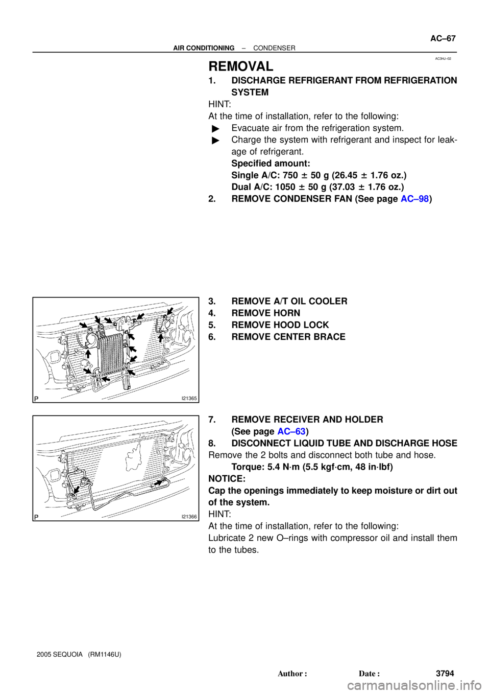
3. REMOVE A/T OIL COOLER
4. REMOVE HORN
5. REMOVE HOOD LOCK
6. REMOVE CENTER BRACE
7. REMOVE RECEIVER AND HOLDER
(See page AC±63)
8. DISCONNECT LIQUID TUBE AND DISCHARGE HOSE
Remove the 2 bolts and disconnect both tube and hose.
Torque: 5.4 N´m (5.5 kgf´cm, 48 in´lbf)
NOTICE:
Cap the openings immediately to keep moisture or dirt out
of the system.
HINT:
At the time of installation, refer to the following:
Lubricate 2 new O±rings with compressor oil and install them
to the tubes.
Page 3804 of 4323
AC1L8±02
± AIR CONDITIONINGCONDENSER
AC±69
3796 Author�: Date�:
2005 SEQUOIA (RM1146U)
INSTALLATION
Installation is in the reverse order of removal (See page AC±67).
Page 3805 of 4323
AC3I8±02
AC±70
± AIR CONDITIONINGREAR A/C EVAPORATOR
3797 Author�: Date�:
2005 SEQUOIA (RM1146U)
REAR A/C EVAPORATOR
ON±VEHICLE INSPECTION
1. CHECK QUANTITY OF GAS DURING REFRIGERATION CYCLE
2. SET MANIFOLD GAUGE SET (See page AC±18)
3. RUN ENGINE
(a) Rear blower speed set at ºHIº position
(b) A/C switch ON
(c) Rear temperature control set at 18.5°C (65°F)
(d) Run the engine at 1,500 rpm for at least 5 minutes.
Then check that the high pressure reading is 1.9 to 2.1 MPa (19 to 21 kgf/cm
2, 270 to 300 psi).
4. CHECK EXPANSION VALVE
If the expansion valve is faulty, the low pressure reading will drop to 0 kPa (0 kgf/cm
2, 0 psi).
Page 3808 of 4323
AC3IA±01
± AIR CONDITIONINGREAR A/C EVAPORATOR
AC±73
3800 Author�: Date�:
2005 SEQUOIA (RM1146U)
INSTALLATION
Installations is in the reverse order of removal (See page AC±71).