Page 3636 of 4323

H16745
a ± a
13.5 mm
(0.531 in.)8 mm (0.31 in.)c ± c
8 mm (0.31 in.) b ± ba
bc a
bc 8 mm (0.31 in.)
13.5 mm
(0.531 in.) Adhesive
Adhesive
Adhesive
± BODYQUARTER WINDOW GLASS
BO±75
3628 Author�: Date�:
2005 SEQUOIA (RM1146U)
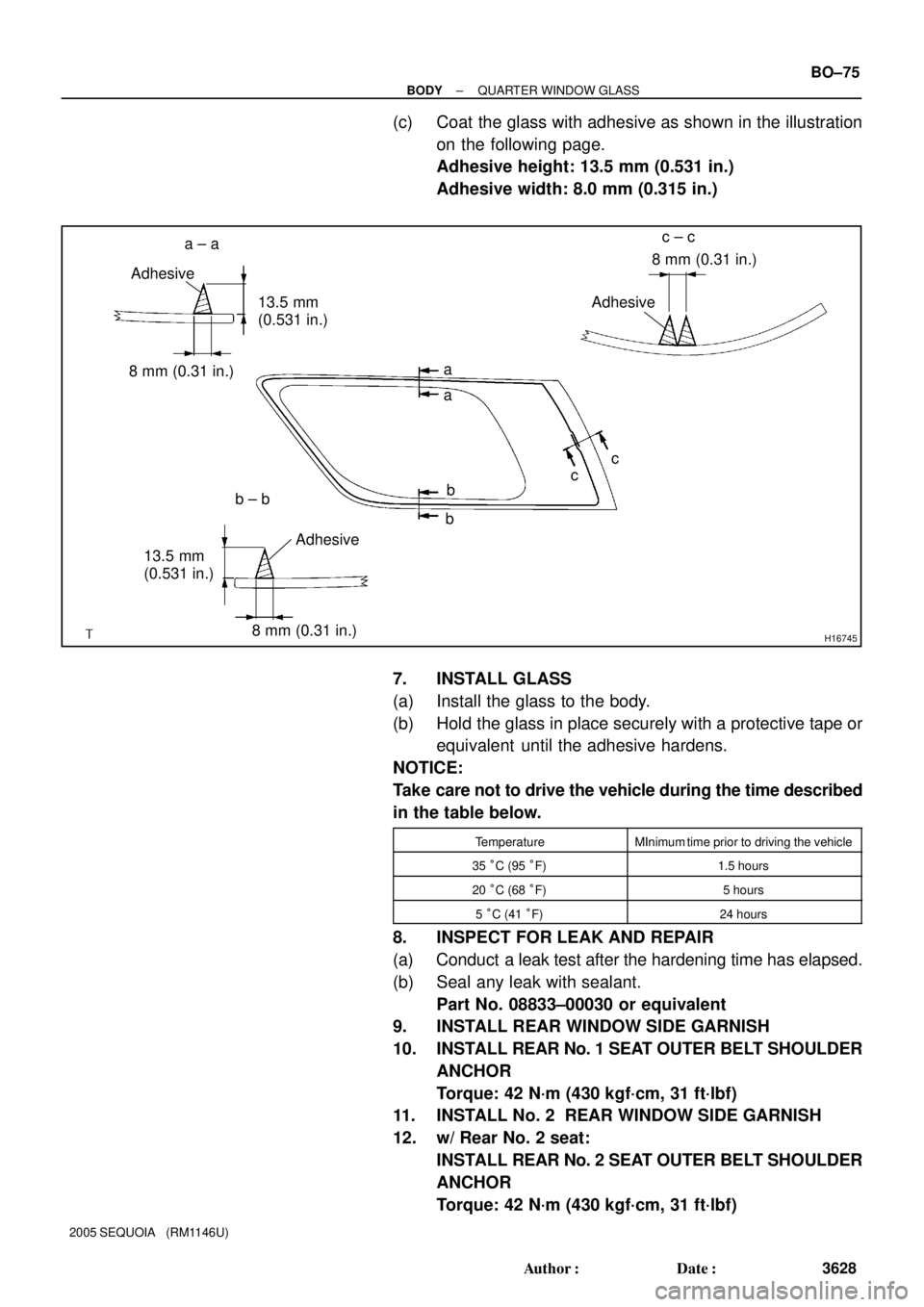
(c) Coat the glass with adhesive as shown in the illustration
on the following page.
Adhesive height: 13.5 mm (0.531 in.)
Adhesive width: 8.0 mm (0.315 in.)
7. INSTALL GLASS
(a) Install the glass to the body.
(b) Hold the glass in place securely with a protective tape or
equivalent until the adhesive hardens.
NOTICE:
Take care not to drive the vehicle during the time described
in the table below.
TemperatureMInimum time prior to driving the vehicle
35 °C (95 °F)1.5 hours
20 °C (68 °F)5 hours
5 °C (41 °F)24 hours
8. INSPECT FOR LEAK AND REPAIR
(a) Conduct a leak test after the hardening time has elapsed.
(b) Seal any leak with sealant.
Part No. 08833±00030 or equivalent
9. INSTALL REAR WINDOW SIDE GARNISH
10. INSTALL REAR No. 1 SEAT OUTER BELT SHOULDER
ANCHOR
Torque: 42 N´m (430 kgf´cm, 31 ft´lbf)
11. INSTALL No. 2 REAR WINDOW SIDE GARNISH
12. w/ Rear No. 2 seat:
INSTALL REAR No. 2 SEAT OUTER BELT SHOULDER
ANCHOR
Torque: 42 N´m (430 kgf´cm, 31 ft´lbf)
Page 3640 of 4323
BO46Q±02
H16774
H16776
± BODYSLIDING ROOF
BO±79
3632 Author�: Date�:
2005 SEQUOIA (RM1146U)
REMOVAL
1. REMOVE ROOF HEADLINING (See page BO±101)
2. REMOVE SLIDING ROOF GLASS ASSEMBLY
(a) Using a torx wrench, remove the 4 screws.
(b) Pull the glass upward to remove it.
3. REMOVE DRIVE GEAR
NOTICE:
Remove the drive gear with the sliding roof fully closed.
(a) Disconnect the connector.
(b) Remove the 2 bolts and drive gear.
(c) Remove the 2 screws and drive gear bracket.
4. REMOVE SLIDING ROOF HOUSING
(a) Disconnect the 4 drain hoses from the housing.
(b) Disengage the wire harness clamps.
(c) Remove the 8 bolts, 2 nuts and sliding roof housing.
Torque: 5.5 N´m (56 kgf´cm, 49 in.´lbf)
Page 3644 of 4323
BO46T±01
± BODYSLIDING ROOF
BO±83
3636 Author�: Date�:
2005 SEQUOIA (RM1146U)
REASSEMBLY
Reassembly is in the reverse order of disassembly (See page BO±80).
Page 3645 of 4323
BO46U±01
BO±84
± BODYSLIDING ROOF
3637 Author�: Date�:
2005 SEQUOIA (RM1146U)
INSTALLATION
Installation is in the reverse order of removal (See page BO±79).
Page 3649 of 4323
H11188
Shape
SizeShapeSize Shape Sizemm (in.)
ù = 5.22
(0.2055)
L = 16
(0.63)
ù = 8
(0.31)ù = 6
(0.24)
L = 14
(0.55)
ù = 5
(0.20)
L = 16
(0.63)ù = 5
(0.20)
L = 16
(0.63)
ù = 6
(0.24) ù = 6
(0.24)
L = 25
(0.98)ù = 8
(0.31)
L = 22
(0.87) BO±88
± BODYINSTRUMENT PANEL
3641 Author�: Date�:
2005 SEQUOIA (RM1146U)
HINT:
Screw shapes and sizes are indicated in the table below. The codes (ºAº ± ºHº) correspond to those indicated
on the previous page.
Page 3650 of 4323

BO4HL±02
H24383Claw
H16716
2 Clips
H16717
Clip
± BODYINSTRUMENT PANEL
BO±89
3642 Author�: Date�:
2005 SEQUOIA (RM1146U)
REMOVAL
1. DISCONNECT CABLE FROM NEGATIVE BATTERY
TERMINAL
Wait for 90 seconds after disconnecting the cable to prevent the
airbag working.
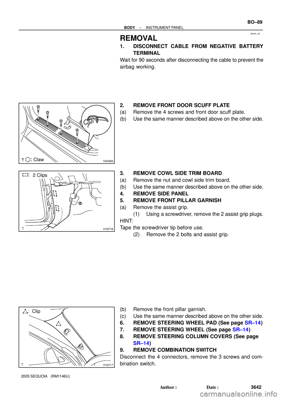
2. REMOVE FRONT DOOR SCUFF PLATE
(a) Remove the 4 screws and front door scuff plate.
(b) Use the same manner described above on the other side.
3. REMOVE COWL SIDE TRIM BOARD
(a) Remove the nut and cowl side trim board.
(b) Use the same manner described above on the other side.
4. REMOVE SIDE PANEL
5. REMOVE FRONT PILLAR GARNISH
(a) Remove the assist grip.
(1) Using a screwdriver, remove the 2 assist grip plugs.
HINT:
Tape the screwdriver tip before use.
(2) Remove the 2 bolts and assist grip.
(b) Remove the front pillar garnish.
(c) Use the same manner described above on the other side.
6. REMOVE STEERING WHEEL PAD (See page SR±14)
7. REMOVE STEERING WHEEL (See page SR±14)
8. REMOVE STEERING COLUMN COVERS (See page
SR±14)
9. REMOVE COMBINATION SWITCH
Disconnect the 4 connectors, remove the 3 screws and com-
bination switch.
Page 3651 of 4323

H11174: 4 Clips
H11372
3 Clips
H11177
2 Clips
H16769
5 Clips
H24384
BO±90
± BODYINSTRUMENT PANEL
3643 Author�: Date�:
2005 SEQUOIA (RM1146U)
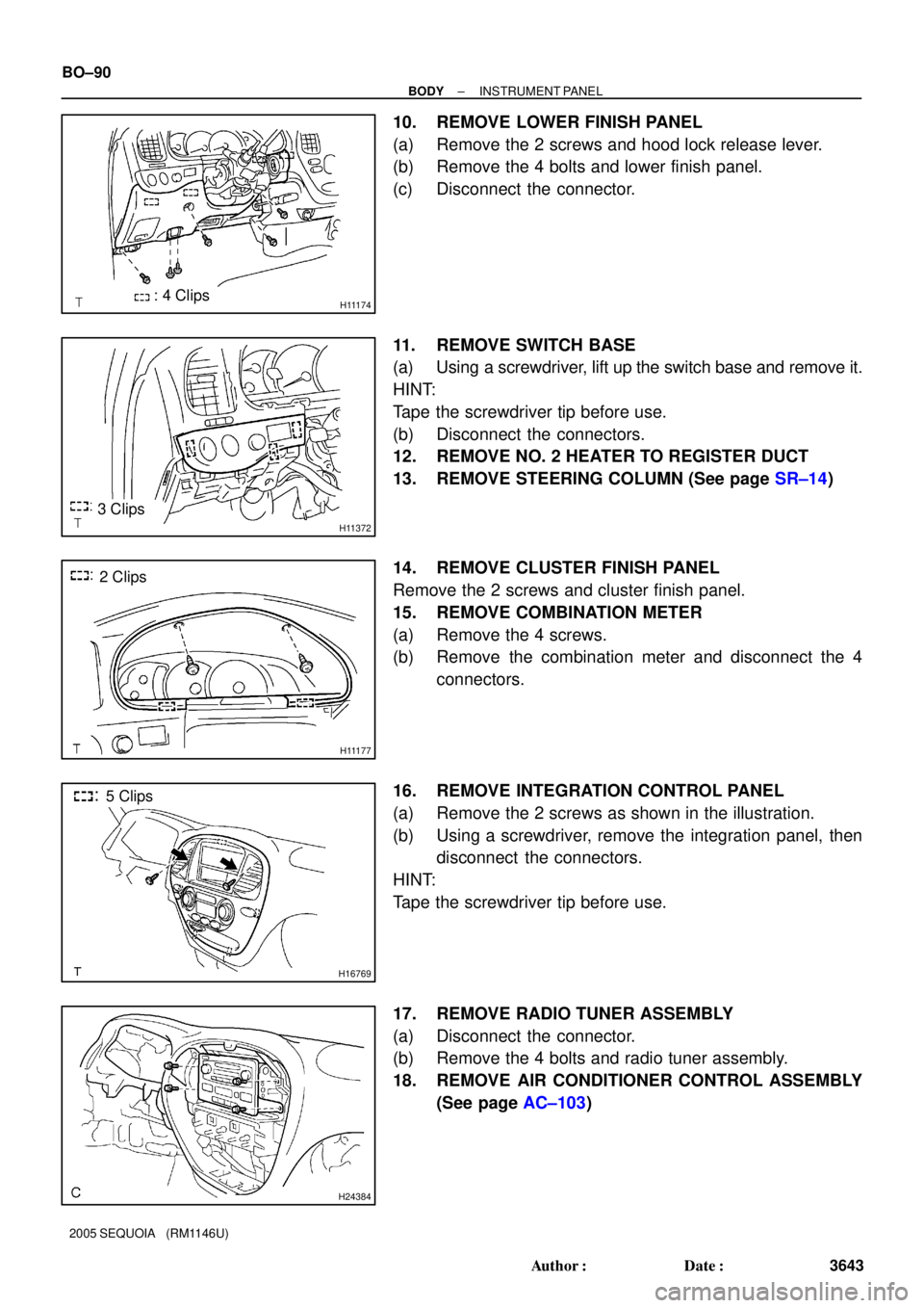
10. REMOVE LOWER FINISH PANEL
(a) Remove the 2 screws and hood lock release lever.
(b) Remove the 4 bolts and lower finish panel.
(c) Disconnect the connector.
11. REMOVE SWITCH BASE
(a) Using a screwdriver, lift up the switch base and remove it.
HINT:
Tape the screwdriver tip before use.
(b) Disconnect the connectors.
12. REMOVE NO. 2 HEATER TO REGISTER DUCT
13. REMOVE STEERING COLUMN (See page SR±14)
14. REMOVE CLUSTER FINISH PANEL
Remove the 2 screws and cluster finish panel.
15. REMOVE COMBINATION METER
(a) Remove the 4 screws.
(b) Remove the combination meter and disconnect the 4
connectors.
16. REMOVE INTEGRATION CONTROL PANEL
(a) Remove the 2 screws as shown in the illustration.
(b) Using a screwdriver, remove the integration panel, then
disconnect the connectors.
HINT:
Tape the screwdriver tip before use.
17. REMOVE RADIO TUNER ASSEMBLY
(a) Disconnect the connector.
(b) Remove the 4 bolts and radio tuner assembly.
18. REMOVE AIR CONDITIONER CONTROL ASSEMBLY
(See page AC±103)
Page 3657 of 4323
BO1MO±03
BO±96
± BODYINSTRUMENT PANEL
3649 Author�: Date�:
2005 SEQUOIA (RM1146U)
REASSEMBLY
Reassembly is in the reverse order of disassembly (See page BO±95).