Page 987 of 4323
F19450
C6
Combination
MeterSuspension Control
ECU
I18
Ignition SW Instrument Panel J/B
Engine Room J/B24
14
15
16 LO
N
HIP
B±L
GR±R26
S25
9
S25
8
S25LO
NR
HI
6
IG2 AM25
W±R B±R IGN1 11
7 1H
1J1C
1C32
W±R
AM2
1
2C
2D1
B
Battery B±O
B 5 4F10
FL Block
± DIAGNOSTICSAIR SUSPENSION SYSTEM
DI±785
979 Author�: Date�:
2005 SEQUOIA (RM1146U)
Height Control Indicator Lamp Circuit
CIRCUIT DESCRIPTION
The height control indicator lamp indicates the target height, not the actual height.
It blinks when the height control is operated by pressing the height control switch and stays on when the
operation is completed.
WIRING DIAGRAM
DIDEL±01
Page 989 of 4323
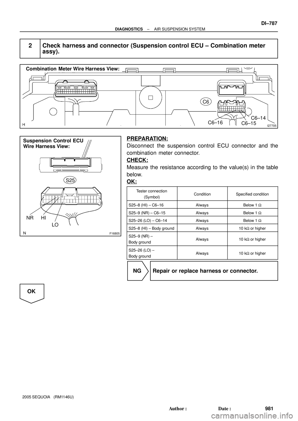
I27705
Combination Meter Wire Harness View:
C6
C6±16
C6±15C6±14
F16805
Suspension Control ECU
Wire Harness View:
S25
NR HI
LO
± DIAGNOSTICSAIR SUSPENSION SYSTEM
DI±787
981 Author�: Date�:
2005 SEQUOIA (RM1146U)
2 Check harness and connector (Suspension control ECU ± Combination meter
assy).
PREPARATION:
Disconnect the suspension control ECU connector and the
combination meter connector.
CHECK:
Measure the resistance according to the value(s) in the table
below.
OK:
Tester connection
(Symbol)ConditionSpecified condition
S25±8 (HI) ± C6±16AlwaysBelow 1 W
S25±9 (NR) ± C6±15AlwaysBelow 1 W
S25±26 (LO) ± C6±14AlwaysBelow 1 W
S25±8 (HI) ± Body groundAlways10 kW or higher
S25±9 (NR) ±
Body groundAlways10 kW or higher
S25±26 (LO) ±
Body groundAlways10 kW or higher
NG Repair or replace harness or connector.
OK
Page 990 of 4323
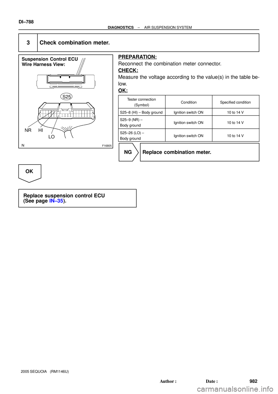
F16805
Suspension Control ECU
Wire Harness View:
S25
NR HI
LO
DI±788
± DIAGNOSTICSAIR SUSPENSION SYSTEM
982 Author�: Date�:
2005 SEQUOIA (RM1146U)
3 Check combination meter.
PREPARATION:
Reconnect the combination meter connector.
CHECK:
Measure the voltage according to the value(s) in the table be-
low.
OK:
Tester connection
(Symbol)ConditionSpecified condition
S25±8 (HI) ± Body groundIgnition switch ON10 to 14 V
S25±9 (NR) ±
Body groundIgnition switch ON10 to 14 V
S25±26 (LO) ±
Body groundIgnition switch ON10 to 14 V
NG Replace combination meter.
OK
Replace suspension control ECU
(See page IN±35).
Page 991 of 4323
F19451
C6
Combination
MeterSuspension Control
ECU
I18
Ignition SW
Engine Room J/B Instrument Panel J/B B±O
W±R11
7 1H
1JIGN1
1C
1C32
B±RMAN. 24
13 LG11
S25 VN
5
IG2 AM2 6
W±R
B
Battery 1
2D AM2
2C1
B5 4F10
FL Block
± DIAGNOSTICSAIR SUSPENSION SYSTEM
DI±789
983 Author�: Date�:
2005 SEQUOIA (RM1146U)
Height Control Manual Indicator Lamp Circuit
CIRCUIT DESCRIPTION
When manual mode is selected by pressing the height control mode select switch, the manual indicator lamp
comes on. (For the wiring diagram of the height control mode select switch circuit, see page DI±778.) If the
suspension control ECU detects a problem, the height control manual indicator lamp blinks while suspend-
ing the height control function. At the same time, the suspension control ECU records a DTC in the memory.
Connect terminals TC and CG of the DLC3 to make the height control manual indicator lamp blink and output
DTCs.
WIRING DIAGRAM
DIDEN±01
Page 993 of 4323
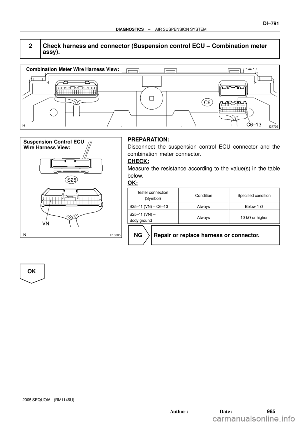
I27705
Combination Meter Wire Harness View:
C6
C6±13
F16805
Suspension Control ECU
Wire Harness View:
S25
VN
± DIAGNOSTICSAIR SUSPENSION SYSTEM
DI±791
985 Author�: Date�:
2005 SEQUOIA (RM1146U)
2 Check harness and connector (Suspension control ECU ± Combination meter
assy).
PREPARATION:
Disconnect the suspension control ECU connector and the
combination meter connector.
CHECK:
Measure the resistance according to the value(s) in the table
below.
OK:
Tester connection
(Symbol)ConditionSpecified condition
S25±11 (VN) ± C6±13AlwaysBelow 1 W
S25±11 (VN) ±
Body groundAlways10 kW or higher
NG Repair or replace harness or connector.
OK
Page 994 of 4323
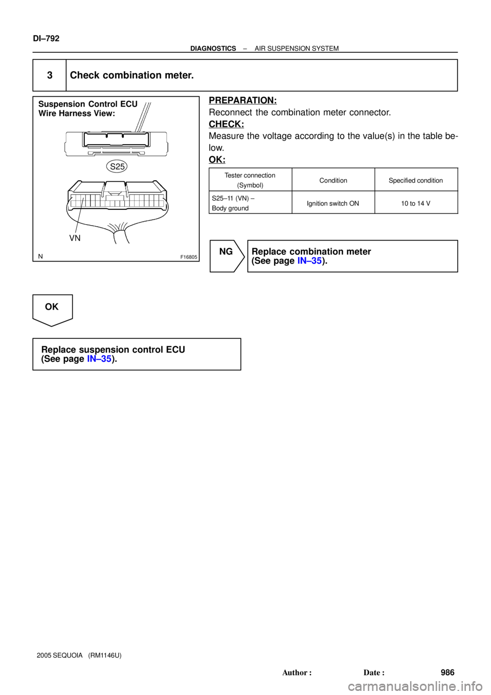
F16805
Suspension Control ECU
Wire Harness View:
S25
VN
DI±792
± DIAGNOSTICSAIR SUSPENSION SYSTEM
986 Author�: Date�:
2005 SEQUOIA (RM1146U)
3 Check combination meter.
PREPARATION:
Reconnect the combination meter connector.
CHECK:
Measure the voltage according to the value(s) in the table be-
low.
OK:
Tester connection
(Symbol)ConditionSpecified condition
S25±11 (VN) ±
Body groundIgnition switch ON10 to 14 V
NG Replace combination meter
(See page IN±35).
OK
Replace suspension control ECU
(See page IN±35).
Page 995 of 4323
F19452
Sub J/B No. 3Suspension Control
ECU
Instrument Panel J/BI18
Ignition SW
F10
FL BlockW±L 2
B
Battery IG1AM11 J37
AJ37
A J/C
B±R
S2510
IG
ALT5 8 W1L1
AM1
11C6 1C4 ECU±IG
1F4 B±R8
3A3C8
2B±YB±R
± DIAGNOSTICSAIR SUSPENSION SYSTEM
DI±793
987 Author�: Date�:
2005 SEQUOIA (RM1146U)
IG Signal Circuit
CIRCUIT DESCRIPTION
The suspension control ECU, controlling the air suspension system, is activated when the ignition switch
is turned ON.
The main relay inside the ECU is activated after 2 seconds and the system is operated by +B power source.
WIRING DIAGRAM
DIDEO±01
Page 996 of 4323
DI±794
± DIAGNOSTICSAIR SUSPENSION SYSTEM
988 Author�: Date�:
2005 SEQUOIA (RM1146U)
INSPECTION PROCEDURE
HINT:
Start the inspection from step 1 when using the hand±held tester, and start from step 2 when not using the
hand±held tester.
1 Read value of the hand±held tester.
PREPARATION:
(a) Connect the hand±held tester to the DLC3.
(b) Turn the ignition switch ON, and push the hand±held tester main switch ON.
(c) Select the item ºIG VOLTAGEº in the DATA LIST, and read its value displayed on the hand±held tester.
AIR SUSPENSION:
ItemMeasurement Item / Range (Dis-
play)Normal ConditionDiagnostic Note
IG VOLTAGEECU power supply voltage / min.:
0 V, max.: 25.5 VActual ECU power supply voltage:
10 to 14 V±
CHECK:
Check the ECU supply voltage.
OK:
Actual ECU power supply voltage: 10 to 14 V
OK Proceed to next circuit inspection shown in
problem symptoms table (See page DI±716).
NG