Page 957 of 4323
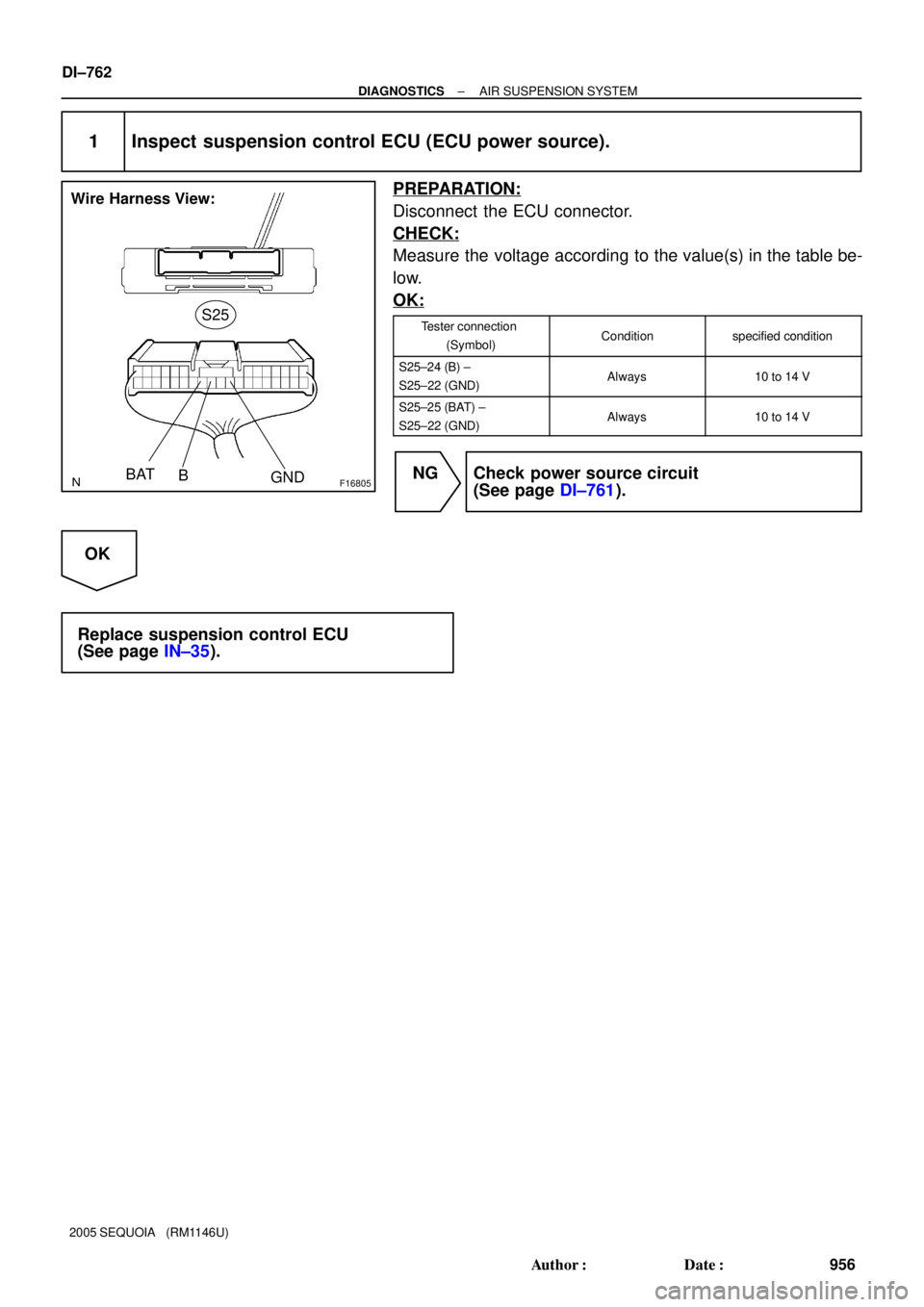
F16805
Suspension Control ECU
Wire Harness View:
S25
RM+
RM±
F19461
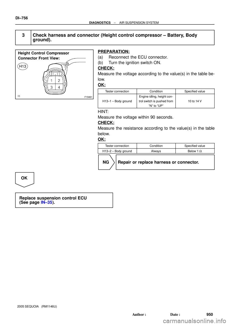
Height Control Compressor
Connector Front View:
H13
± DIAGNOSTICSAIR SUSPENSION SYSTEM
DI±755
949 Author�: Date�:
2005 SEQUOIA (RM1146U)
2 Check harness and connector (height control compressor ± Suspension control
ECU).
PREPARATION:
Disconnect the ECU connector.
CHECK:
Check for an open or short circuit in the harness and the con-
nector between terminals 3 and 4 of the height control compres-
sor and terminals S25±20 (RM+) and S25±21 (RM±) of the sus-
pension control ECU.
OK:
There is no open or short in the wire harness.
NG Repair or replace harness or connector.
OK
Page 958 of 4323
F19461
Height Control Compressor
Connector Front View:
H13
DI±756
± DIAGNOSTICSAIR SUSPENSION SYSTEM
950 Author�: Date�:
2005 SEQUOIA (RM1146U)
3 Check harness and connector (Height control compressor ± Battery, Body
ground).
PREPARATION:
(a) Reconnect the ECU connector.
(b) Turn the ignition switch ON.
CHECK:
Measure the voltage according to the value(s) in the table be-
low.
OK:
Tester connectionConditionSpecified value
H13±1 ± Body ground
Engine idling, height con-
trol switch is pushed from
ºNº to ºUPº
10 to 14 V
HINT:
Measure the voltage within 90 seconds.
CHECK:
Measure the resistance according to the value(s) in the table
below.
OK:
Tester connectionConditionSpecified value
H13±2 ± Body groundAlwaysBelow 1 W
NG Repair or replace harness or connector.
OK
Replace suspension control ECU
(See page IN±35).
Page 959 of 4323

DTC C1751/51 Continuous Electric Current To Height Con-
trol Compressor
CIRCUIT DESCRIPTION
DTC No.DTC Detectin")
± DIAGNOSTICSAIR SUSPENSION SYSTEM
DI±757
951 Author�: Date�:
2005 SEQUOIA (RM1146U)
DTC C1751/51 Continuous Electric Current To Height Con-
trol Compressor
CIRCUIT DESCRIPTION
DTC No.DTC Detecting ConditionTrouble Area
C1751/51*1With the AIR SUS relay activated, the vehicle does not go up
to the standard vehicle height after the 90 sec. have elapsed.
�Height control compressor assy
�Height control compressor circuit
�Height control sensor circuit
�Height control sensor sub±assy
�Relief valve
�AIR SUS relay circuit
�Air leakage from the air tube or each valve
�Clogging in the air tube or each valve
�Suspension control ECU
*1: The compressor motor operates continuously to raise vehicle height and allows electric current flow to
the AIR SUS relay for 90 seconds or more under the following conditions:
�Vehicle height control is attempted on a steep slope when the vehicle is overloaded.
�The compressor remains on for an excessive period of time or repeatedly turns on and off because
of continuous height control switch operation.
�If the compressor remains on because the vehicle is jacked up, the vehicle height is set at a position
lower than normal while the engine is running and then the vehicle height control function raises the
vehicle.
Thus DTC C1751/51 may be output and vehicle height control may be suspended. (This is not electrically
abnormal.) In this case, however, the vehicle height operation is resumed approx. 10 min. after the ignition
switch is turned ON after the ECU detects the first error. If ECU detects another error, it takes 70 minutes
until control is resumed.
WIRING DIAGRAM
See page DI±752.
DIDDV±01
Page 962 of 4323

NG Replace height control valve assy
(See page SA±162).
NG Replace height control compressor assy
(See page SA")
DI±760
± DIAGNOSTICSAIR SUSPENSION SYSTEM
954 Author�: Date�:
2005 SEQUOIA (RM1146U)
NG Replace height control valve assy
(See page SA±162).
NG Replace height control compressor assy
(See page SA±162).
OK
4 Inspect height control sensor sub±assy.
CHECK:
Inspect and adjust the height control sensor sub±assy (See page SA±156).
NEXT
5 Reconfirm DTC.
CHECK:
Clear the DTC and repeat the procedure to re±check it (See page DI±729).
HINT:
If the DTC C1751/51 is still output, proceed to the next step.
NEXT
Check and repair or replace malfunctioning
parts.
(a) Air tube is clogged (See page SA±156).
(b) Compressor is faulty (See page SA±162).
(c) Relief valve is faulty (See page SA±166).
(d) Height control sensor sub±assy is faulty (See page SA±156).
(e) Foreign material entered the height control solenoid valve (gate solenoid valve) and the exhaust sole-
noid valve.
(f) Air leakage due to damage to the height control cylinder assy (pneumatic cylinder).
(g) Suspension control ECU malfunctions (See page IN±35).
Page 963 of 4323

DTC C1761/61 ECU Malfunction
CIRCUIT DESCRIPTION
DTC No.DTC Detecting ConditionTrouble Area
C1761/61Suspension")
± DIAGNOSTICSAIR SUSPENSION SYSTEM
DI±761
955 Author�: Date�:
2005 SEQUOIA (RM1146U)
DTC C1761/61 ECU Malfunction
CIRCUIT DESCRIPTION
DTC No.DTC Detecting ConditionTrouble Area
C1761/61Suspension control ECU malfunction
�Power source circuit
�Suspension control ECU
�Communication circuit
INSPECTION PROCEDURE
HINT:
�If DTC C1774/74 (power source circuit) is displayed, perform the inspection necessary for DTC
C1774/74 first (See page DI±763).
�If DTC U0122/67, U0100/65, U0132/71 and C1761/61 (ECU malfunction) are output at the same time,
perform the inspection necessary for the CAN communication system first.
�The suspension control ECU, controlling the air suspension system, is activated when the ignition
switch is turned ON.
After 2 seconds, the ºMAIN RELAYº built in the ECU is activated and the system is driven by +B power
source.
Vehicle height may increase after turning the ignition switch off and unloading the vehicle/letting
people get out of the vehicle. In order to adjust the vehicle height, vehicle height control will continue
for a while from then.
DIDDY±01
Page 964 of 4323
F16805
S25
Wire Harness View:
BAT
B
GND
DI±762
± DIAGNOSTICSAIR SUSPENSION SYSTEM
956 Author�: Date�:
2005 SEQUOIA (RM1146U)
1 Inspect suspension control ECU (ECU power source).
PREPARATION:
Disconnect the ECU connector.
CHECK:
Measure the voltage according to the value(s) in the table be-
low.
OK:
Tester connection
(Symbol)Conditionspecified condition
S25±24 (B) ±
S25±22 (GND)Always10 to 14 V
S25±25 (BAT) ±
S25±22 (GND)Always10 to 14 V
NG Check power source circuit
(See page DI±761).
OK
Replace suspension control ECU
(See page IN±35).
Page 965 of 4323
F19445
Engine Room R/B No. 2
F10
Fusible Link BlockSuspension Control
ECU
AIR SUS No. 2
2
1
22 W
AIR SUS
9ALT
5B
Battery
IFJ12
J/C
AW±B22
S25
GND 24
S25
25
S25
BAT B J/C
B
J37
B
J37 C
J38 V
IA55
VV
V
± DIAGNOSTICSAIR SUSPENSION SYSTEM
DI±763
957 Author�: Date�:
2005 SEQUOIA (RM1146U)
DTC C1774/74 Power Source Circuit
CIRCUIT DESCRIPTION
�This circuit provides power to operate the suspension control ECU.
�The suspension control ECU, controlling the air suspension system, is activated when the ignition
switch is turned ON. The main relay inside the ECU is activated after 2 seconds and the system is oper-
ated by +B power source.
DTC No.DTC Detecting ConditionTrouble Area
C1774/74The terminal B or BAT voltage is below 10 V or above 16 V for
0.5 seconds.�Battery
�Power source circuit
�Suspension control ECU
WIRING DIAGRAM
DIDE3±01
Page 967 of 4323
F16805
S25
BAT
B
Wire Harness View:
± DIAGNOSTICSAIR SUSPENSION SYSTEM
DI±765
959 Author�: Date�:
2005 SEQUOIA (RM1146U)
A
3 Inspect fuse (AIR SUS No. 2).
PREPARATION:
Remove the AIR SUS No. 2 fuse from the engine room R/B.
CHECK:
Check continuity of the AIR SUS No. 2 fuse.
OK:
Continuity
NG Inspect for short circuit in all harness and com-
ponents connected to AIR SUS No. 2 fuse.
OK
4 Inspect suspension control ECU.
PREPARATION:
Disconnect the ECU connector.
CHECK:
Measure the voltage between terminal S25±24 (B) of the sus-
pension control ECU connector and body ground and between
terminal S25±25 (BAT) and body ground.
OK:
Voltage: 10 to 14 V
NG Repair or replace harness or connector.
OK