Page 3143 of 4323
SA174±05
SA0627
± SUSPENSION AND AXLECOIL SPRING AND REAR SHOCK ABSORBER
SA±139
3135 Author�: Date�:
2005 SEQUOIA (RM1146U)
INSPECTION
Normal Type:
INSPECT SHOCK ABSORBER
Compress and extend the shock absorber rod and check that
there is no abnormal resistance or unusual operation sounds.
If there is any abnormality, replace the shock absorber with a
new one.
Page 3201 of 4323
BR±26
± BRAKEFRONT BRAKE PAD
3193 Author�: Date�:
2005 SEQUOIA (RM1146U)
HINT:
Apply disc brake grease to both sides of inner anti±squeal
shims (See page BR±24).
(d) Install new pads.
NOTICE:
Do not allow oil or grease to get on the rubbing face.
7. INSTALL ANTI±RATTLE SPRING AND 2 PINS
8. INSTALL CLIP
9. INSTALL FRONT WHEEL
Torque: 110 N´m (1,122 kgf´cm, 81 ft´lbf)
10. DEPRESS BRAKE PEDAL SEVERAL TIMES
11. CHECK THAT FLUID LEVEL IS AT MAX LINE
Page 3209 of 4323

BR0TB±07
F13313
F13314
BR±34
± BRAKEREAR BRAKE PAD
3201 Author�: Date�:
2005 SEQUOIA (RM1146U)
REPLACEMENT
1. REMOVE REAR WHEEL
2. INSPECT PAD LINING THICKNESS
Check the pad thickness through the caliper inspection hole
and replace pads if not within the specification.
Minimum thickness: 1.0 mm (0.039 in.)
3. REMOVE BRAKE CALIPER
(a) Remove the 2 sliding pins.
(b) Remove the caliper and suspend it so the hose is not
stretched.
HINT:
Do not disconnect the flexible hose.
4. REMOVE 2 PADS WITH 2 ANTI±SQUEAL SHIMS
5. REMOVE 4 PAD SUPPORT PLATES
NOTICE:
The pad support plates can be used again provided that
they have sufficient rebound, no deformation, cracks or
wear, and have had all rust, dirt and foreign particles
cleaned off.
6. CHECK DISC THICKNESS AND RUNOUT
(See page BR±39)
7. INSTALL PAD SUPPORT PLATES
8. INSTALL NEW PADS
NOTICE:
When replacing worn pads, the anti±squeal shims must be
replaced together with the pads.
(a) Install the pad wear indicator plate on new inner pad.
(b) Install the anti±squeal shim on each pad.
(c) Install the inner pad with the pad wear indicator plate fac-
ing downward.
(d) Install outer pad.
NOTICE:
There should be no oil or grease adhering to the friction
surfaces of the pads or the disc.
9. INSTALL CALIPER
(a) Draw out a small amount of brake fluid from the reservoir.
Page 3241 of 4323

F13254
INOUTAttachment
Pressure Feed Tube
SST
Z15498
Oil
Reservoir
PS Vane
Pump PS Gear
SST Closed
Z15499
Oil
Reservoir
PS Vane
Pump PS Gear
SST Open SR±6
± STEERINGPOWER STEERING FLUID
3233 Author�: Date�:
2005 SEQUOIA (RM1146U)
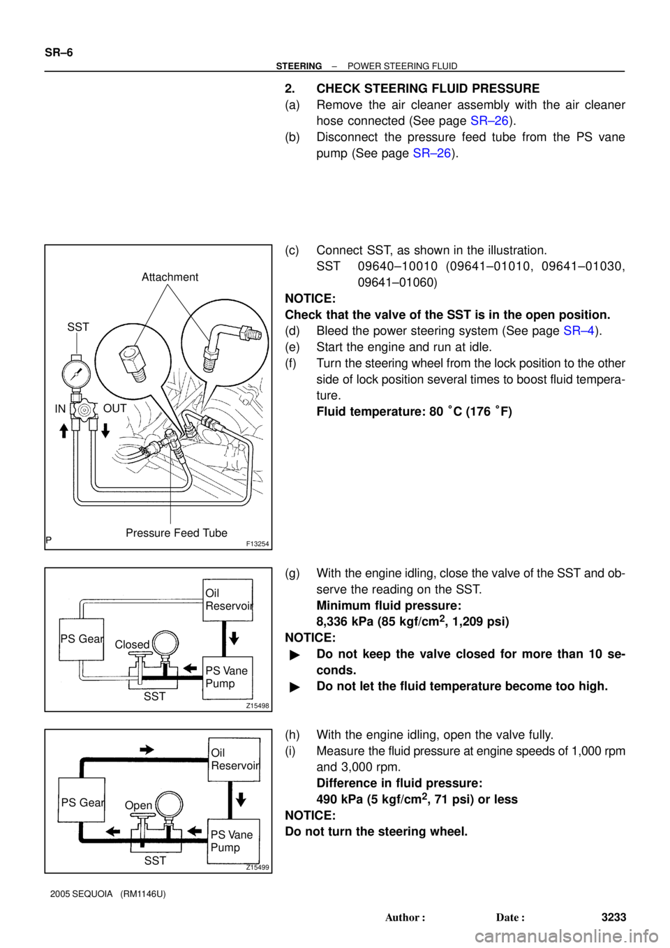
2. CHECK STEERING FLUID PRESSURE
(a) Remove the air cleaner assembly with the air cleaner
hose connected (See page SR±26).
(b) Disconnect the pressure feed tube from the PS vane
pump (See page SR±26).
(c) Connect SST, as shown in the illustration.
SST 09640±10010 (09641±01010, 09641±01030,
09641±01060)
NOTICE:
Check that the valve of the SST is in the open position.
(d) Bleed the power steering system (See page SR±4).
(e) Start the engine and run at idle.
(f) Turn the steering wheel from the lock position to the other
side of lock position several times to boost fluid tempera-
ture.
Fluid temperature: 80 °C (176 °F)
(g) With the engine idling, close the valve of the SST and ob-
serve the reading on the SST.
Minimum fluid pressure:
8,336 kPa (85 kgf/cm
2, 1,209 psi)
NOTICE:
�Do not keep the valve closed for more than 10 se-
conds.
�Do not let the fluid temperature become too high.
(h) With the engine idling, open the valve fully.
(i) Measure the fluid pressure at engine speeds of 1,000 rpm
and 3,000 rpm.
Difference in fluid pressure:
490 kPa (5 kgf/cm
2, 71 psi) or less
NOTICE:
Do not turn the steering wheel.
Page 3254 of 4323

SR0V2±05
F13613
F13618
R11908
± STEERINGTILT STEERING COLUMN
SR±19
3246 Author�: Date�:
2005 SEQUOIA (RM1146U)
INSPECTION
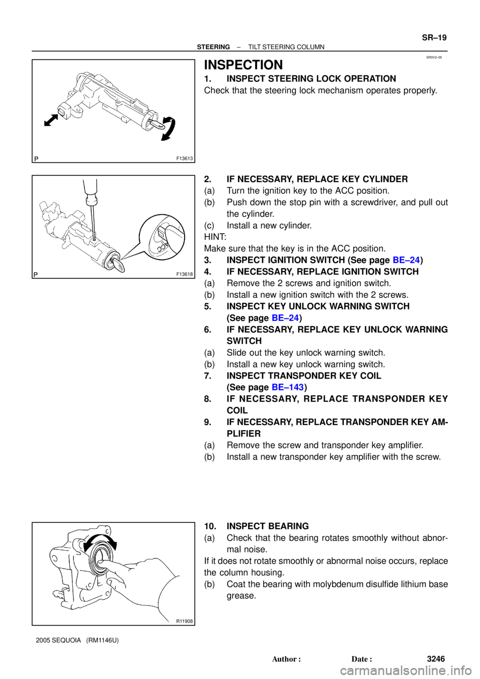
1. INSPECT STEERING LOCK OPERATION
Check that the steering lock mechanism operates properly.
2. IF NECESSARY, REPLACE KEY CYLINDER
(a) Turn the ignition key to the ACC position.
(b) Push down the stop pin with a screwdriver, and pull out
the cylinder.
(c) Install a new cylinder.
HINT:
Make sure that the key is in the ACC position.
3. INSPECT IGNITION SWITCH (See page BE±24)
4. IF NECESSARY, REPLACE IGNITION SWITCH
(a) Remove the 2 screws and ignition switch.
(b) Install a new ignition switch with the 2 screws.
5. INSPECT KEY UNLOCK WARNING SWITCH
(See page BE±24)
6. IF NECESSARY, REPLACE KEY UNLOCK WARNING
SWITCH
(a) Slide out the key unlock warning switch.
(b) Install a new key unlock warning switch.
7. INSPECT TRANSPONDER KEY COIL
(See page BE±143)
8. IF NECESSARY, REPLACE TRANSPONDER KEY
COIL
9. IF NECESSARY, REPLACE TRANSPONDER KEY AM-
PLIFIER
(a) Remove the screw and transponder key amplifier.
(b) Install a new transponder key amplifier with the screw.
10. INSPECT BEARING
(a) Check that the bearing rotates smoothly without abnor-
mal noise.
If it does not rotate smoothly or abnormal noise occurs, replace
the column housing.
(b) Coat the bearing with molybdenum disulfide lithium base
grease.
Page 3265 of 4323
SR0RF±05
F06719
Vane Pump Shaft
Front HousingBushing
N00372
HeightThickness
Length
R10282
Feeler Gauge
SR±30
± STEERINGPOWER STEERING VANE PUMP
3257 Author�: Date�:
2005 SEQUOIA (RM1146U)
INSPECTION
1. CHECK OIL CLEARANCE BETWEEN VANE PUMP
SHAFT AND BUSHING
Using a micrometer and caliper gauge, measure the oil clear-
ance.
Standard clearance:
0.03 to 0.05 mm (0.0012 to 0.0020 in.)
Maximum clearance: 0.07 mm (0.0028 in.)
If it is more than the maximum, replace the shaft and front hous-
ing.
2. INSPECT VANE PUMP ROTOR AND VANE PLATES
(a) Using a micrometer, measure the height, thickness and
length of the 10 plates.
Minimum height: 8.6 mm (0.339 in.)
Minimum thickness: 1.397 mm (0.0550 in.)
Minimum length: 14.991 mm (0.5902 in.)
(b) Using a feeler gauge, measure the clearance between
the rotor groove and plate.
Maximum clearance: 0.033 mm (0.0013 in.)
Page 3285 of 4323

R11656
SST
Wire
Cylinder End
Stopper
F06757
SST
F06758
Vinyl Tape
F08339Oil Seal SST
SR±50
± STEERINGPOWER STEERING GEAR
3277 Author�: Date�:
2005 SEQUOIA (RM1146U)
5. INSTALL CYLINDER END STOPPER
(a) Align the installation hole for the wire of the stopper with
the slot of the rack housing.
(b) Install a new wire into the stopper.
(c) Using SST, turn the stopper clockwise 400° to 500°.
SST 09631±16010
6. AIR TIGHTNESS TEST
(a) Install SST to the rack housing.
SST 09631±12071
(b) Apply 53 kPa (400 mmHg, 15.75 in.Hg) of vacuum for
about 30 seconds.
(c) Check that there is no change in the vacuum.
If there is change in the vacuum, check the installation of the oil
seals.
7. INSTALL CONTROL VALVE ASSEMBLY
(a) To prevent oil seal lip damage, wind vinyl tape on the ser-
rated part of the valve shaft.
(b) Coat the teflon rings with power steering fluid.
(c) Install the valve assembly into the valve housing.
NOTICE:
Be careful not to damage the teflon rings and oil seal.
8. INSTALL OIL SEAL
(a) Coat a new oil seal lip with power steering fluid.
(b) Using SST, press in the oil seal.
SST 09612±22011
NOTICE:
Make sure to install the oil seal in the correct direction.
9. INSTALL CONTROL VALVE HOUSING WITH CON-
TROL VALVE ASSEMBLY
(a) Place a new gasket on the rack housing.
(b) Align the matchmarks on the control valve housing with
the one on the rack housing.
(c) Install the 2 bolts.
Torque: 18 N´m (185 kgf´cm, 13 ft´lbf)
Page 3459 of 4323
BE25W±04
I21525
Free Pushed in
I18556
I04053
± BODY ELECTRICALSTOP LIGHT SYSTEM
BE±47
3451 Author�: Date�:
2005 SEQUOIA (RM1146U)
INSPECTION
1. INSPECT STOP LIGHT SWITCH CONTINUITY
Switch positionTester connectionSpecified condition
Switch pin free1 ± 4Continuity
Switch pin pushed in1 ± 4No continuity
Switch pin free2 ± 3No continuity
Switch pin pushed in2 ± 3Continuity
If continuity is not as specified, replace the switch.
2. w/ Rear Spoiler:
INSPECT HI±MOUNTED STOP LIGHT ASSEMBLY
CONTINUITY
Using the ohmmeter, check that continuity exists between ter-
minal 1 and terminal 2.
If continuity is not as specified, replace the light assembly.
3. w/o Rear Spoiler:
INSPECT HI±MOUNTED STOP LIGHT ASSEMBLY
CONTINUITY
Using the ohmmeter, check that continuity exists between ter-
minal 1 and terminal 2.
If continuity is not as specified, replace the light assembly.