Page 3463 of 4323

I01935
4 3
I01936
4 5
I01937
1
2
4 5
I18560
Front Washer Motor:
2
Rear Washer Motor:1
2
1
± BODY ELECTRICALWIPER AND WASHER SYSTEM
BE±51
3455 Author�: Date�:
2005 SEQUOIA (RM1146U)
6. High Speed:
INSPECT WIPER MOTOR OPERATION
Connect the positive (+) lead from the battery to terminal 3 and
the negative (±) lead from the battery to the motor body or termi-
nal 4, and check that the motor operates at high speed.
If operation is not as specified, replace the motor.
7. Stopping at Stop Position:
INSPECT WIPER MOTOR OPERATION
(a) Operate the motor at low speed and stop the motor opera-
tion anywhere except at the stop position by disconnect-
ing positive (+) lead from terminal 5.
(b) Connect terminals 1 and 5.
(c) Connect the positive (+) lead from the battery to terminal
2 and the negative (±) lead from the battery to the motor
body or terminal 4, and check that the motor stops run-
ning at the stop position after the motor operates again.
If operation is not as specified, replace the motor.
8. INSPECT WASHER MOTOR OPERATION
Connect the positive (+) lead from the battery to terminal 2 and
the negative (±) lead to terminal 1, and check that the motor op-
erates.
NOTICE:
These tests must be performed quickly (within 20 seconds)
to prevent the coil from burning out.
If operation is not as specified, replace the motor.
Page 3468 of 4323

I21530
Ignition
Switch
Battery(Wire Harness Side)(3.4W) Fuel Gauge
Z05730
Warning Light
Ignition
Switch
Battery
1
23
45
Wire
Harness Side:
I28772
I01278
BE±56
± BODY ELECTRICALCOMBINATION METER
3460 Author�: Date�:
2005 SEQUOIA (RM1146U)
(c) Connect terminals 2 and 3 on the wire harness side con-
nector through a 3.4 watts test bulb.
(d) Turn the ignition switch ON, check that the bulb comes on
and the receiver gauge needle moves towards the full
side.
HINT:
Because of silicon oil in the gauge, it will take a short time for
the needle to stabilize.
If operation is not as specified, inspect the receiver gauge resis-
tance.
4. INSPECT FUEL LEVEL WARNING LIGHT OPERATION
(a) Disconnect the connector from the sender gauge.
(b) Connect terminals 2 and 3 on the wire harness side con-
nector.
(c) Turn the ignition switch ON and check that the warning
light comes on.
If the warning light does not come on, test the bulb or inspect
the wire harness.
5. INSPECT ENGINE COOLANT TEMPERATURE SEND-
ER GAUGE RESISTANCE
(a) Disconnect the engine coolant temperature sender
gauge.
(b) Measure the resistance between terminals 1 and 2 of the
connector according to the value(s) in the table below.
Temperature °C (°F)Resistance (W)
±20 (±4)13,840 to 16,330
20 (68)2,320 to 2,590
80 (176)310 to 326
110 (230)139.9 to 143.5
If resistance value is not as specified, replace the engine cool-
ant sender gauge.
6. INSPECT OIL PRESSURE SENDER OPERATION
(a) Disconnect the connector from the oil pressure sender.
(b) Check that no continuity exists between terminal and
ground with the engine stopped.
(c) Check that continuity exists between terminal and ground
with the engine running.
HINT:
Oil pressure should be over 24.5 kPa (0.25 kgf/cm
2, 3.55 psi).
If operation is not as specified, replace the oil pressure sender.
Page 3555 of 4323
BE2D6±02
I10154
I24870
12
6
± BODY ELECTRICALENGINE IMMOBILISER SYSTEM
BE±143
3547 Author�: Date�:
2005 SEQUOIA (RM1146U)
INSPECTION
1. INSPECTION TRANSPONDER KEY COIL CONTINU-
ITY
Check that there is continuity between terminals 1 and 2.
If continuity is not as specified, replace the coil.
2. INSPECT TRANSPONDER KEY ECU CIRCUIT
Connect the wire harness side connector to the ECU and in-
spect the wire harness side connector from the back side, as
shown in the table below.
ConditionTester connectionSpecified condition
Always6 ± 12Battery positive voltage
If the circuit is as specified, replace the ECU with a new one.
If the circuit is not as specified, inspect the circuit connected to
other parts.
Page 3742 of 4323

I22614
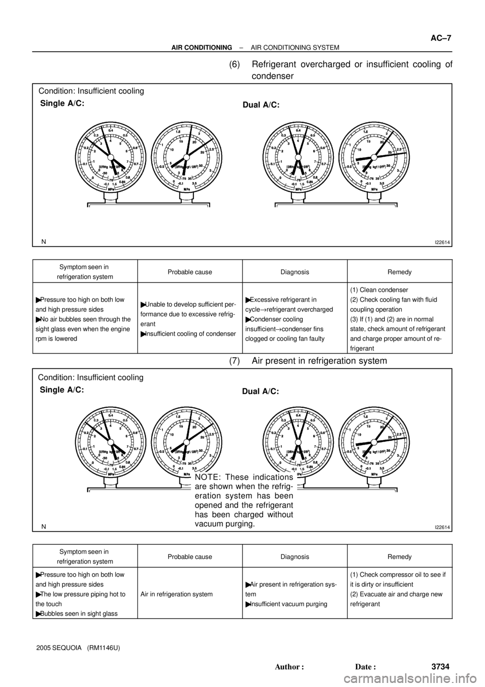
Condition: Insufficient cooling
Single A/C:
Dual A/C:
I22614
Condition: Insufficient cooling
Single A/C:
Dual A/C:
NOTE: These indications
are shown when the refrig-
eration system has been
opened and the refrigerant
has been charged without
vacuum purging.
± AIR CONDITIONINGAIR CONDITIONING SYSTEM
AC±7
3734 Author�: Date�:
2005 SEQUOIA (RM1146U)
(6) Refrigerant overcharged or insufficient cooling of
condenser
Symptom seen in
refrigeration systemProbable causeDiagnosisRemedy
� Pressure too high on both low
and high pressure sides
� No air bubbles seen through the
sight glass even when the engine
rpm is lowered� Unable to develop sufficient per-
formance due to excessive refrig-
erant
� Insufficient cooling of condenser� Excessive refrigerant in
cycle"refrigerant overcharged
� Condenser cooling
insufficient"condenser fins
clogged or cooling fan faulty
(1) Clean condenser
(2) Check cooling fan with fluid
coupling operation
(3) If (1) and (2) are in normal
state, check amount of refrigerant
and charge proper amount of re-
frigerant
(7) Air present in refrigeration system
Symptom seen in
refrigeration systemProbable causeDiagnosisRemedy
� Pressure too high on both low
and high pressure sides
� The low pressure piping hot to
the touch
� Bubbles seen in sight glass
Air in refrigeration system
� Air present in refrigeration sys-
tem
� Insufficient vacuum purging
(1) Check compressor oil to see if
it is dirty or insufficient
(2) Evacuate air and charge new
refrigerant
Page 3762 of 4323
I06919
Disconnect the tube
by hand
Screwdriver
Tube
I06878
Connect Wrong
Gap
I21374
± AIR CONDITIONINGCOOLING UNIT
AC±27
3754 Author�: Date�:
2005 SEQUOIA (RM1146U)
NOTICE:
�Do not use tools like a screwdriver to remove the
tube.
�Cap the openings immediately to keep moisture or
dirt out of the system.
HINT:
At the time of reassembly, refer to the following:
�Lubricate 4 new O±rings with compressor oil and install
them to the tubes.
�After connection, check the claw of the piping clamp is se-
curely engaged.
3. REMOVE CONSOLE UPPER PANEL
4. REMOVE REAR CONSOLE BOX
5. REMOVE FRONT CONSOLE BOX
6. REMOVE GLOVE COMPARTMENT PARTS
7. REMOVE LOWER NO. 2 FINISH PANEL
8. REMOVE LOWER LH FINISH PANEL
9. REMOVE LOWER COVER (See page BO±89)
10. REMOVE NO. 4 HEATER TO REGISTER DUCT
11. REMOVE COOLING UNIT
(a) Disconnect the connectors.
(b) Remove the 3 screws and the bolt, then the cooling unit.
Page 3789 of 4323

AC1KZ±05
I21361
3
3
I21362
12
AC±54
± AIR CONDITIONINGCOMPRESSOR AND MAGNETIC CLUTCH
3781 Author�: Date�:
2005 SEQUOIA (RM1146U)
COMPRESSOR AND MAGNETIC
CLUTCH
ON±VEHICLE INSPECTION
1. SET MANIFOLD GAUGE SET (See page AC±18)
2. START ENGINE
3. INSPECT COMPRESSOR FOR METALLIC SOUND
Check if a metallic sound can be heard from the compressor
when the A/C switch is on.
If a metallic sound cannot be heard, replace the compressor as-
sembly.
4. INSPECT REFRIGERANT PRESSURE
(See page AC±3)
5. STOP ENGINE
6. INSPECT VISUALLY FOR LEAKAGE OF REFRIGER-
ANT FROM SAFETY SEAL
Using a gas leak detector, check for leakage of refrigerant.
If there is any leakage, replace the compressor assembly.
7. REMOVE MANIFOLD GAUGE SET
(See page AC±19)
8. CHECK FOR LEAKAGE OF GREASE FROM CLUTCH
BEARING
9. CHECK FOR SIGNS OF OIL ON PRESSURE PLATE
If necessary, repair or replace.
10. INSPECT MAGNETIC CLUTCH BEARING FOR NOISE
(a) Start the engine.
(b) Check if abnormal noise is heard from near the compres-
sor when the A/C switch is OFF.
If abnormal noise is being emitted, replace the magnetic clutch.
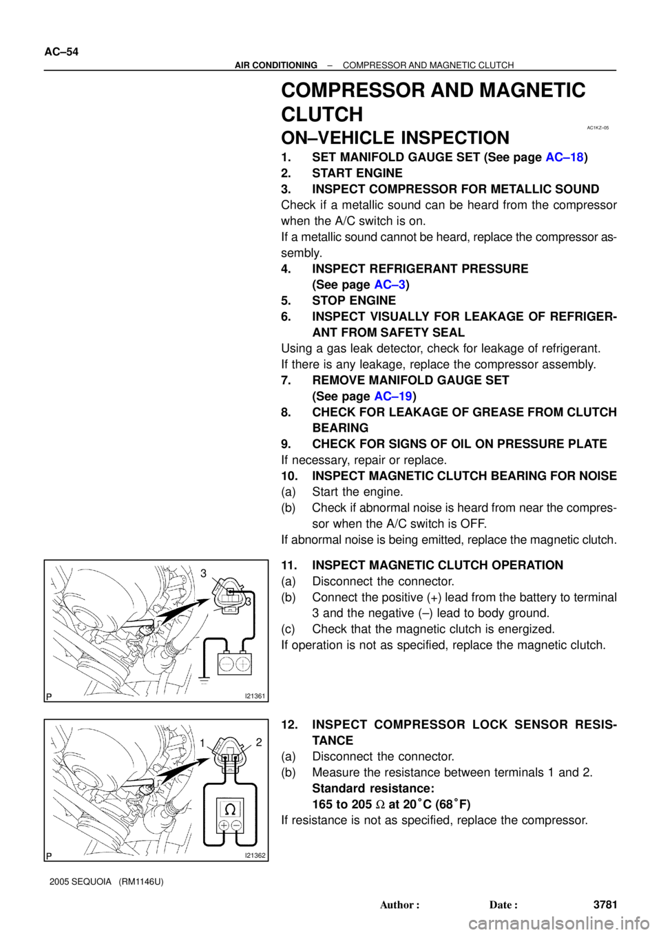
11. INSPECT MAGNETIC CLUTCH OPERATION
(a) Disconnect the connector.
(b) Connect the positive (+) lead from the battery to terminal
3 and the negative (±) lead to body ground.
(c) Check that the magnetic clutch is energized.
If operation is not as specified, replace the magnetic clutch.
12. INSPECT COMPRESSOR LOCK SENSOR RESIS-
TANCE
(a) Disconnect the connector.
(b) Measure the resistance between terminals 1 and 2.
Standard resistance:
165 to 205 W at 20°C (68°F)
If resistance is not as specified, replace the compressor.
Page 3796 of 4323

AC3HF±02
± AIR CONDITIONINGCOMPRESSOR AND MAGNETIC CLUTCH
AC±61
3788 Author�: Date�:
2005 SEQUOIA (RM1146U)
INSTALLATION
1. INSTALL COMPRESSOR
(a) Install the compressor with the cooler bracket with the 3 bolts and nut.
Torque:
Bolt: 47 N´m (480 kgf´cm, 35 in.´lbf)
Nut: 25 N´m (255 kgf´cm, 18 in.´lbf)
(b) Connect the connector.
2. CONNECT DISCHARGE AND SUCTION HOSES
Connect both hoses with the 2 nuts.
Torque: 10 N´m (100 kgf´cm, 7 in.´lbf)
NOTICE:
Hoses should be connected immediately after the caps have been removed.
HINT:
Lubricate 2 new O±rings with compressor oil and install them to the hoses.
3. INSTALL AND CHECK DRIVE BELT (See page AC±17, AC±15)
4. CONNECT CABLE TO NEGATIVE BATTERY TERMINAL
5. EVACUATE AIR FROM REFRIGERATION SYSTEM
6. CHARGE SYSTEM WITH REFRIGERANT
Specified amount:
Single A/C: 750 ± 50g (26.45 ± 1.76 oz.)
Dual A/C: 1050 ± 50g (37.03 ± 1.76 oz.)
7. INSPECT FOR LEAKAGE OF REFRIGERANT
Using a gas leak detector, check for leakage of refrigerant.
If there is leakage, check the tightening torque at the joints.
8. PERFORM INITIALIZATION (See page IN±20)
Some systems need initialization when disconnecting the cable from the negative battery terminal.
Page 3883 of 4323

05_SEQUOIA_U (L/O 0408)
24
2005 SEQUOIA from Aug. '04 Prod. (OM34424U)
3. Put in a new transmitter battery with
positive (+) side up.
Close the transmitter case securely.
NOTICE
�Make sure the positive side and
negative side of the transmitter bat-
tery are faced correctly.
�Do not replace the battery with wet
hands. Water may cause unexpected
rust.
�Do not touch or move any compo-
nents inside the transmitter, or it
may interfere with proper operation.
�Be careful not to bend the electrode
when inserting the transmitter bat-
tery and that dust or oils do not
adhere to the transmitter case.
�Close the transmitter case securely.
After replacing the battery, check that the
transmitter operates properly. If the trans-
mitter still does not operate properly, con-
tact your Toyota dealer.
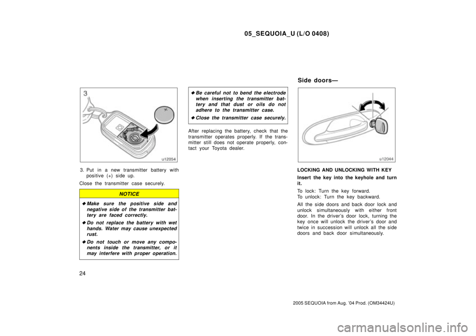
LOCKING AND UNLOCKING WITH KEY
Insert the key into the keyhole and turn
it.
To lock: Turn the key forward.
To unlock: Turn the key backward.
All the side doors and back door lock and
unlock simultaneously with either front
door. In the driver 's door lock, turning the
key once will unlock the driver's door and
twice in succession will unlock all the side
doors and back door simultaneously.
Side doorsÐ