Page 2771 of 4323

SST (Union)
Fuel Return Hose
B00884
SST
(Adaptor)
SST
(Hose)
SST
(Clamp)
Vinyl
HoseO±Ring
D13872
Hand�")
SF134±04
B07326
SST
InjectorSST
SST
SST
Pressure Regulator
B04988
Pressure Regulator
SST (Hose)
SST (Union)
Fuel Return Hose
B00884
SST
(Adaptor)
SST
(Hose)
SST
(Clamp)
Vinyl
HoseO±Ring
D13872
Hand±Held Tester
DLC3
CAN VIM
± SFIINJECTOR
SF±29
2763 Author�: Date�:
2005 SEQUOIA (RM1146U)
INSPECTION
1. INSPECT INJECTOR INJECTION
CAUTION:
Keep the injector clean of sparks during the test.
(a) Disconnect the fuel inlet hose (fuel tube connector) from
the fuel filter.
(b) Connect SST (attachment and hose) to the fuel tube.
SST 09268±41047 (09268±52011)
(c) Remove the pressure regulator from the delivery pipe.
(d) Install the O±ring to the fuel inlet of the pressure regulator.
(e) Connect SST (hose) to the fuel inlet of the pressure regu-
lator with SST (union) and the 2 bolts.
SST 09268±41047 (09268±41091)
Torque: 7.5 N´m (76 kgf´cm, 66 in.´lbf)
(f) Connect the fuel return hose to the fuel outlet of the pres-
sure regulator.
(g) Install the O±ring to the injector.
(h) Connect SST (adaptor and hose) to the injector, and hold
the injector and union with SST (clamp).
SST 09268±41047 (09268±41110, 09268±41300)
(i) Put the injector into the graduated cylinder.
CAUTION:
Install a suitable vinyl hose onto the injector to prevent
gasoline from splashing out.
(j) Connect a hand±held tester to the Controller Area Net-
work Vehicle Interface Module (CAN VIM). Then connect
the CAN VIM to the Date Link Connector 3 (DLC3).
(k) Connect the battery negative (±) cable to the battery.
(l) Turn the ignition switch ON, and push the hand±held tes-
ter main switch ON.
NOTICE:
Do not start the engine.
(m) Enter the following menus: DIAGNOSIS / ENHANCED
OBDII / ACTIVE TEST / FUEL PUMP / SPD
(n) Please refer to the hand±held tester operator's manual
for further details.
Page 2774 of 4323
B07534
Clamp
Clamp
B16540
(a)(c)
(b)
Throttle Body Cover Bracket
SF±32
± SFIINJECTOR
2766 Author�: Date�:
2005 SEQUOIA (RM1146U)
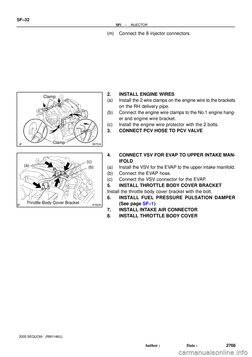
(m) Connect the 8 injector connectors.
2. INSTALL ENGINE WIRES
(a) Install the 2 wire clamps on the engine wire to the brackets
on the RH delivery pipe.
(b) Connect the engine wire clamps to the No.1 engine hang-
er and engine wire bracket.
(c) Install the engine wire protector with the 2 bolts.
3. CONNECT PCV HOSE TO PCV VALVE
4. CONNECT VSV FOR EVAP TO UPPER INTAKE MAN-
IFOLD
(a) Install the VSV for the EVAP to the upper intake manifold.
(b) Connect the EVAP hose.
(c) Connect the VSV connector for the EVAP.
5. INSTALL THROTTLE BODY COVER BRACKET
Install the throttle body cover bracket with the bolt.
6. INSTALL FUEL PRESSURE PULSATION DAMPER
(See page SF±1)
7. INSTALL INTAKE AIR CONNECTOR
8. INSTALL THROTTLE BODY COVER
Page 2776 of 4323
SF1XH±01
B17581
B17582
B17583
SF±34
± SFIFUEL TANK AND LINE
2768 Author�: Date�:
2005 SEQUOIA (RM1146U)
REMOVAL
1. DISCHARGE FUEL SYSTEM PRESSURE
(See page SF±1)
2. REMOVE SPARE TIRE
3. DISCONNECT FUEL PUMP CONNECTOR
4. REMOVE FUEL TANK PROTECTOR
Remove the 2 bolts, 2 nuts and fuel tank protector.
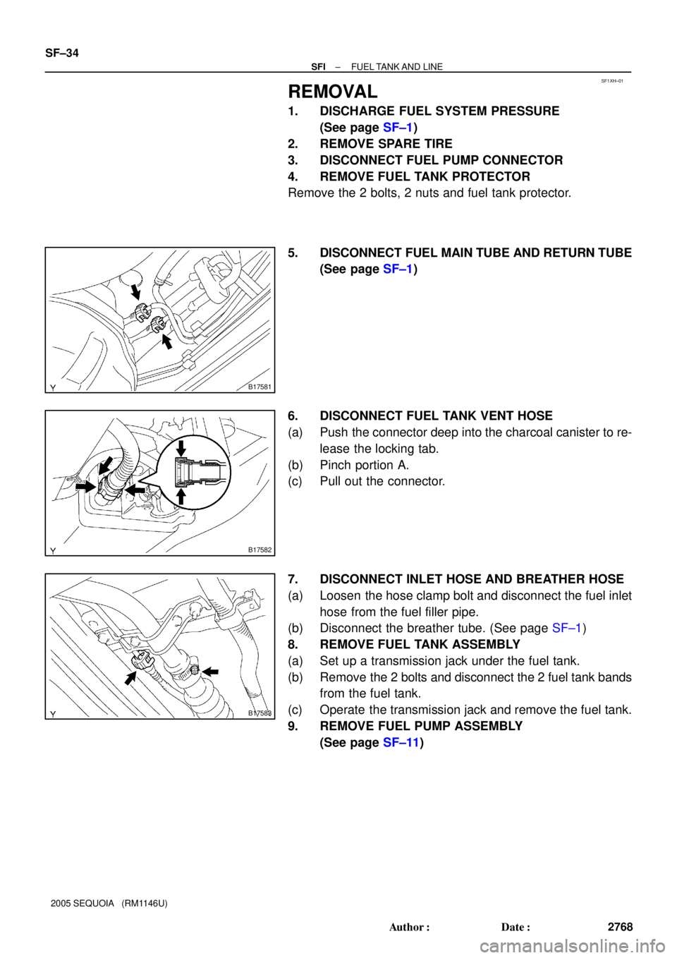
5. DISCONNECT FUEL MAIN TUBE AND RETURN TUBE
(See page SF±1)
6. DISCONNECT FUEL TANK VENT HOSE
(a) Push the connector deep into the charcoal canister to re-
lease the locking tab.
(b) Pinch portion A.
(c) Pull out the connector.
7. DISCONNECT INLET HOSE AND BREATHER HOSE
(a) Loosen the hose clamp bolt and disconnect the fuel inlet
hose from the fuel filler pipe.
(b) Disconnect the breather tube. (See page SF±1)
8. REMOVE FUEL TANK ASSEMBLY
(a) Set up a transmission jack under the fuel tank.
(b) Remove the 2 bolts and disconnect the 2 fuel tank bands
from the fuel tank.
(c) Operate the transmission jack and remove the fuel tank.
9. REMOVE FUEL PUMP ASSEMBLY
(See page SF±11)
Page 3468 of 4323
(3.4W) Fuel Gauge
Z05730
Warning Light
Ignition
Switch
Battery
1
23
45
Wire
Harness Side:
I28772
I01278
BE±56
± BODY ELECTRICALCOMBINATION METER
346")
I21530
Ignition
Switch
Battery(Wire Harness Side)(3.4W) Fuel Gauge
Z05730
Warning Light
Ignition
Switch
Battery
1
23
45
Wire
Harness Side:
I28772
I01278
BE±56
± BODY ELECTRICALCOMBINATION METER
3460 Author�: Date�:
2005 SEQUOIA (RM1146U)
(c) Connect terminals 2 and 3 on the wire harness side con-
nector through a 3.4 watts test bulb.
(d) Turn the ignition switch ON, check that the bulb comes on
and the receiver gauge needle moves towards the full
side.
HINT:
Because of silicon oil in the gauge, it will take a short time for
the needle to stabilize.
If operation is not as specified, inspect the receiver gauge resis-
tance.
4. INSPECT FUEL LEVEL WARNING LIGHT OPERATION
(a) Disconnect the connector from the sender gauge.
(b) Connect terminals 2 and 3 on the wire harness side con-
nector.
(c) Turn the ignition switch ON and check that the warning
light comes on.
If the warning light does not come on, test the bulb or inspect
the wire harness.
5. INSPECT ENGINE COOLANT TEMPERATURE SEND-
ER GAUGE RESISTANCE
(a) Disconnect the engine coolant temperature sender
gauge.
(b) Measure the resistance between terminals 1 and 2 of the
connector according to the value(s) in the table below.
Temperature °C (°F)Resistance (W)
±20 (±4)13,840 to 16,330
20 (68)2,320 to 2,590
80 (176)310 to 326
110 (230)139.9 to 143.5
If resistance value is not as specified, replace the engine cool-
ant sender gauge.
6. INSPECT OIL PRESSURE SENDER OPERATION
(a) Disconnect the connector from the oil pressure sender.
(b) Check that no continuity exists between terminal and
ground with the engine stopped.
(c) Check that continuity exists between terminal and ground
with the engine running.
HINT:
Oil pressure should be over 24.5 kPa (0.25 kgf/cm
2, 3.55 psi).
If operation is not as specified, replace the oil pressure sender.
Page 3736 of 4323

AIR CONDITIONING SYSTEM
PRECAUTION
1. DO NOT HANDLE")
AC2810
AC1JS±06
AC2811
N11084
Wrong Okay
HI LO HILO
± AIR CONDITIONINGAIR CONDITIONING SYSTEM
AC±1
3728 Author�: Date�:
2005 SEQUOIA (RM1146U)
AIR CONDITIONING SYSTEM
PRECAUTION
1. DO NOT HANDLE REFRIGERANT IN AN ENCLOSED
AREA OR NEAR AN OPEN FLAME
2. ALWAYS WEAR EYE PROTECTION
3. BE CAREFUL NOT TO GET LIQUID REFRIGERANT IN
YOUR EYES OR ON YOUR SKIN
If liquid refrigerant gets in your eyes or on your skin.
(a) Wash the area with lots of cool water.
CAUTION:
Do not rub your eyes or skin.
(b) Apply clean petroleum jelly to the skin.
(c) Go immediately to a physician or hospital for professional
treatment.
4. NEVER HEAT CONTAINER OR EXPOSE IT TO OPEN
FLAME
5. BE CAREFUL NOT TO DROP CONTAINER OR NOT TO
APPLY PHYSICAL SHOCKS TO IT
6. DO NOT OPERATE COMPRESSOR WITHOUT
ENOUGH REFRIGERANT IN REFRIGERATION SYS-
TEM
If there is not enough refrigerant in the refrigerant system, oil lu-
brication will be insufficient and compressor burnout may occur.
Necessary care should be taken to avoid this.
7. DO NOT OPEN PRESSURE MANIFOLD VALVE WHILE
COMPRESSOR IS OPERATING
If the high pressure valve is opened, refrigerant flows in the re-
verse direction and could cause the charging cylinder to rup-
ture, so open and close only the low pressure valve.
8. BE CAREFUL NOT TO OVERCHARGE SYSTEM WITH
REFRIGERANT
If refrigerant is overcharged, it causes problems such as insuffi-
cient cooling, poor fuel economy, engine overheating, etc.
Page 3856 of 4323
05_SEQUOIA_U (L/O 0408)
vii
2005 SEQUOIA from Aug. '04 Prod. (OM34424U)
Spark ignition system of your
To y o t a
The spark ignition system in your Toyota meets all re-
quirements of the Canadian Interference±Causing Equip-
ment Standard.
Installation of a mobile
two±way radio system
As the installation of a mobile two±way radio system in
your vehicle could affect electronic systems such as
multiport fuel injection system/sequential multiport fuel
injection system, electronic throttle control system,
cruise control system, anti±lock brake system, traction
control system (two±wheel drive models)/active traction
control system (four±wheel drive models), vehicle stabil-
ity control system, rear height control air suspension
system, tire pressure warning system, SRS airbag sys-
tem and seat belt pretensioner system, be sure to
check with your Toyota dealer for precautionary mea-
sures or special instructions regarding installation.
Page 3867 of 4323
05_SEQUOIA_U (L/O 0408)
8
2005 SEQUOIA from Aug. '04 Prod. (OM34424U)
1. Service reminder indicators and
indicator lights
2. Oil pressure gauge
3. Tachometer4. Speedometer
5. Fuel gauge
6. Engine coolant temperature gauge7. Trip meter reset knob
8. Odometer and two trip meters
9. Height control indicator lights
10. Volt meter
Instrument cluster overview
�Ty p e A
Page 3868 of 4323
05_SEQUOIA_U (L/O 0408)
9
2005 SEQUOIA from Aug. '04 Prod. (OM34424U)
1. Service reminder indicators and
indicator lights
2. Oil pressure gauge
3. Tachometer4. Speedometer
5. Fuel gauge
6. Engine coolant temperature gauge7. Trip meter reset knob
8. Odometer and two trip meters
9. Height control indicator lights
10. Volt meter �Ty p e B

vii
2005 SEQUOIA from Aug. 04 Prod. (OM34424U)
Spark ignition system of your
To y o t a
The spark ignition system in your Toyota meets all re-
quirements of the Canadian Inter")

8
2005 SEQUOIA from Aug. 04 Prod. (OM34424U)
1. Service reminder indicators and
indicator lights
2. Oil pressure gauge
3. Tachometer4. Speedometer
5. Fuel gauge
6. Engine cool")

9
2005 SEQUOIA from Aug. 04 Prod. (OM34424U)
1. Service reminder indicators and
indicator lights
2. Oil pressure gauge
3. Tachometer4. Speedometer
5. Fuel gauge
6. Engine cool")