Page 2625 of 4323
A23328
A23329
A23330
(a)(a)
(b)(c)
(c) (c)
B17510
A23331
EM±38
± ENGINE MECHANICALCYLINDER HEAD
2617 Author�: Date�:
2005 SEQUOIA (RM1146U)
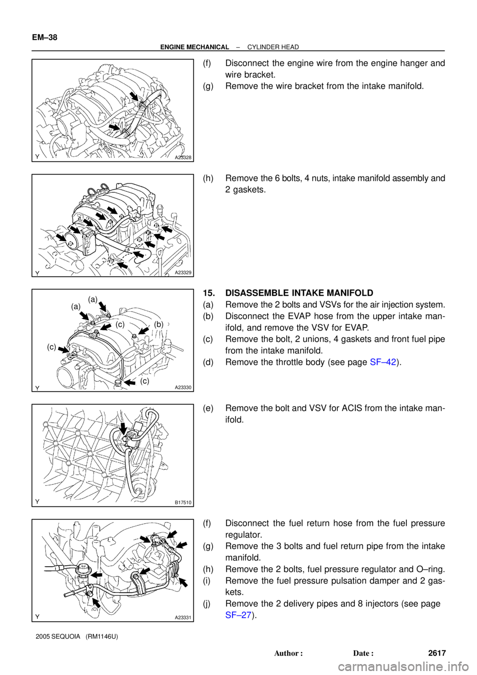
(f) Disconnect the engine wire from the engine hanger and
wire bracket.
(g) Remove the wire bracket from the intake manifold.
(h) Remove the 6 bolts, 4 nuts, intake manifold assembly and
2 gaskets.
15. DISASSEMBLE INTAKE MANIFOLD
(a) Remove the 2 bolts and VSVs for the air injection system.
(b) Disconnect the EVAP hose from the upper intake man-
ifold, and remove the VSV for EVAP.
(c) Remove the bolt, 2 unions, 4 gaskets and front fuel pipe
from the intake manifold.
(d) Remove the throttle body (see page SF±42).
(e) Remove the bolt and VSV for ACIS from the intake man-
ifold.
(f) Disconnect the fuel return hose from the fuel pressure
regulator.
(g) Remove the 3 bolts and fuel return pipe from the intake
manifold.
(h) Remove the 2 bolts, fuel pressure regulator and O±ring.
(i) Remove the fuel pressure pulsation damper and 2 gas-
kets.
(j) Remove the 2 delivery pipes and 8 injectors (see page
SF±27).
Page 2658 of 4323
A04015
Wire
Clamp
Bracket
A23333
Rear Water Bypass Joint
A23332
Front Water Bypass Joint
A23331
± ENGINE MECHANICALCYLINDER HEAD
EM±71
2650 Author�: Date�:
2005 SEQUOIA (RM1146U)
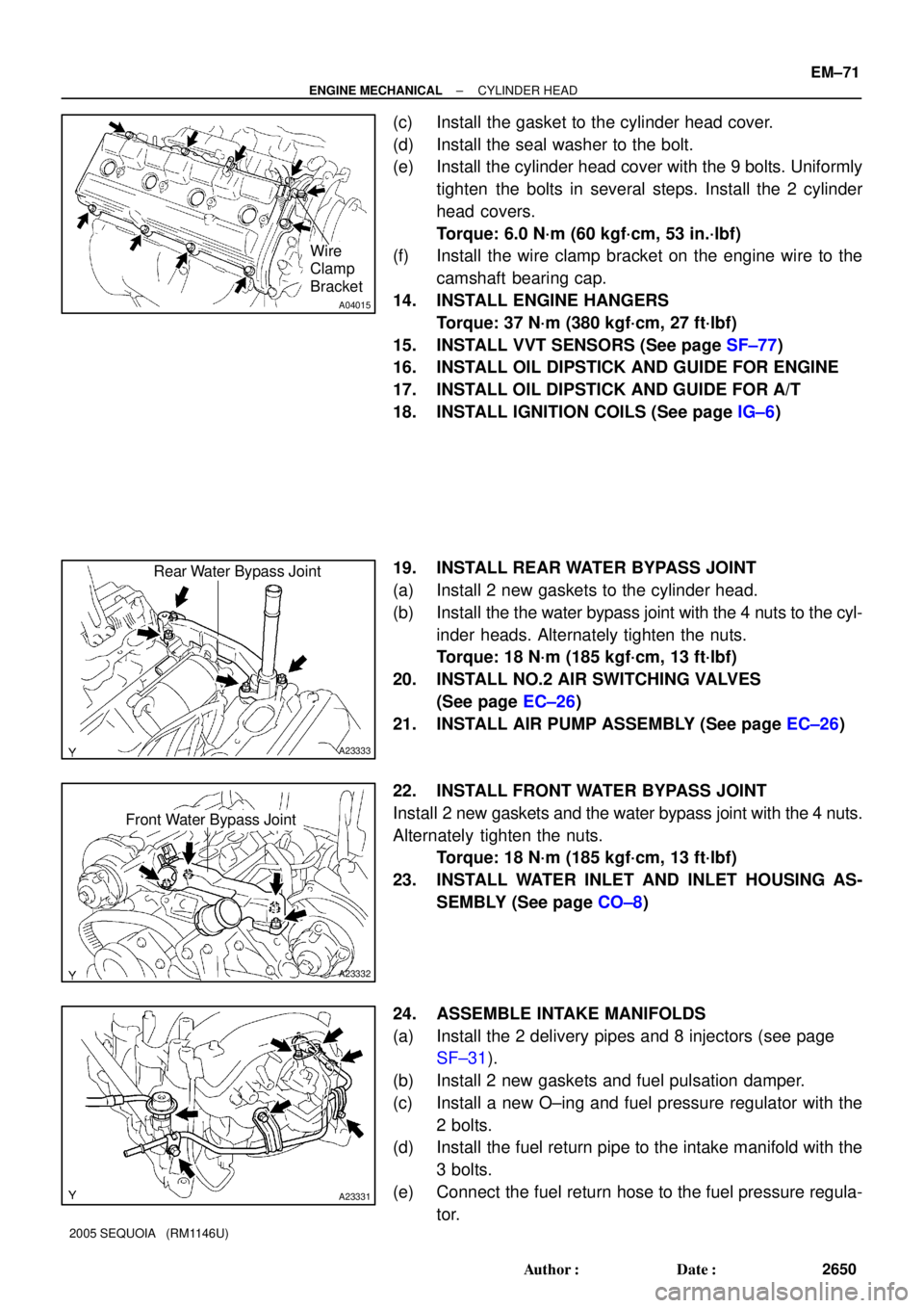
(c) Install the gasket to the cylinder head cover.
(d) Install the seal washer to the bolt.
(e) Install the cylinder head cover with the 9 bolts. Uniformly
tighten the bolts in several steps. Install the 2 cylinder
head covers.
Torque: 6.0 N´m (60 kgf´cm, 53 in.´lbf)
(f) Install the wire clamp bracket on the engine wire to the
camshaft bearing cap.
14. INSTALL ENGINE HANGERS
Torque: 37 N´m (380 kgf´cm, 27 ft´lbf)
15. INSTALL VVT SENSORS (See page SF±77)
16. INSTALL OIL DIPSTICK AND GUIDE FOR ENGINE
17. INSTALL OIL DIPSTICK AND GUIDE FOR A/T
18. INSTALL IGNITION COILS (See page IG±6)
19. INSTALL REAR WATER BYPASS JOINT
(a) Install 2 new gaskets to the cylinder head.
(b) Install the the water bypass joint with the 4 nuts to the cyl-
inder heads. Alternately tighten the nuts.
Torque: 18 N´m (185 kgf´cm, 13 ft´lbf)
20. INSTALL NO.2 AIR SWITCHING VALVES
(See page EC±26)
21. INSTALL AIR PUMP ASSEMBLY (See page EC±26)
22. INSTALL FRONT WATER BYPASS JOINT
Install 2 new gaskets and the water bypass joint with the 4 nuts.
Alternately tighten the nuts.
Torque: 18 N´m (185 kgf´cm, 13 ft´lbf)
23. INSTALL WATER INLET AND INLET HOUSING AS-
SEMBLY (See page CO±8)
24. ASSEMBLE INTAKE MANIFOLDS
(a) Install the 2 delivery pipes and 8 injectors (see page
SF±31).
(b) Install 2 new gaskets and fuel pulsation damper.
(c) Install a new O±ing and fuel pressure regulator with the
2 bolts.
(d) Install the fuel return pipe to the intake manifold with the
3 bolts.
(e) Connect the fuel return hose to the fuel pressure regula-
tor.
Page 2661 of 4323
A23324
(a)
(b)
(c)
(d)
EM±74
± ENGINE MECHANICALCYLINDER HEAD
2653 Author�: Date�:
2005 SEQUOIA (RM1146U)
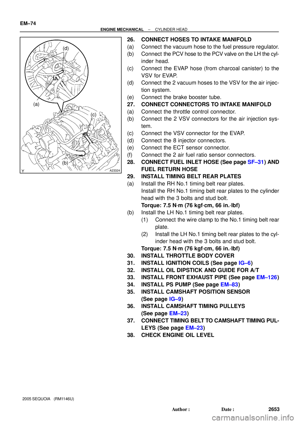
26. CONNECT HOSES TO INTAKE MANIFOLD
(a) Connect the vacuum hose to the fuel pressure regulator.
(b) Connect the PCV hose to the PCV valve on the LH the cyl-
inder head.
(c) Connect the EVAP hose (from charcoal canister) to the
VSV for EVAP.
(d) Connect the 2 vacuum hoses to the VSV for the air injec-
tion system.
(e) Connect the brake booster tube.
27. CONNECT CONNECTORS TO INTAKE MANIFOLD
(a) Connect the throttle control connector.
(b) Connect the 2 VSV connectors for the air injection sys-
tem.
(c) Connect the VSV connector for the EVAP.
(d) Connect the 8 injector connectors.
(e) Connect the ECT sensor connector.
(f) Connect the 2 air fuel ratio sensor connectors.
28. CONNECT FUEL INLET HOSE (See page SF±31) AND
FUEL RETURN HOSE
29. INSTALL TIMING BELT REAR PLATES
(a) Install the RH No.1 timing belt rear plates.
Install the RH No.1 timing belt rear plates to the cylinder
head with the 3 bolts and stud bolt.
Torque: 7.5 N´m (76 kgf´cm, 66 in.´lbf)
(b) Install the LH No.1 timing belt rear plates.
(1) Connect the wire clamp to the No.1 timing belt rear
plate.
(2) Install the LH No.1 timing belt rear plates to the cyl-
inder head with the 3 bolts and stud bolt.
Torque: 7.5 N´m (76 kgf´cm, 66 in.´lbf)
30. INSTALL THROTTLE BODY COVER
31. INSTALL IGNITION COILS (See page IG±6)
32. INSTALL OIL DIPSTICK AND GUIDE FOR A/T
33. INSTALL FRONT EXHAUST PIPE (See page EM±126)
34. INSTALL PS PUMP (See page EM±83)
35. INSTALL CAMSHAFT POSITION SENSOR
(See page IG±9)
36. INSTALL CAMSHAFT TIMING PULLEYS
(See page EM±23)
37. CONNECT TIMING BELT TO CAMSHAFT TIMING PUL-
LEYS (See page EM±23)
38. CHECK ENGINE OIL LEVEL
Page 2667 of 4323
A09151
A08905
A08907
EM±80
± ENGINE MECHANICALENGINE UNIT (2WD)
2659 Author�: Date�:
2005 SEQUOIA (RM1146U)
(d) Disconnect the hose clamp for the PS air hose.
(e) Disconnect the PS air hose from the upper intake man-
ifold.
(f) Disconnect the 2 heater hoses.
(g) Disconnect the ground strap from the cowl panel.
(h) Disconnect the fuel inlet hose and clamps.
(i) Disconnect the fuel return hose and clamp.
(j) Disconnect the air inlet hose from the charcoal canister.
(k) Disconnect the EVAP hose from the charcoal canister.
(l) w/o Hydraulic brake booster:
Disconnect the brake booster tube.
11. REMOVE FRONT EXHAUST PIPES
(See page EM±126)
12. REMOVE PROPELLER SHAFT (See page PR±3)
13. REMOVE FRONT STABILIZER BAR
(See page SA±91)
14. DISCONNECT POWER STEERING GEAR PIPES
Disconnect the pressure feed tube, turn tube and pressure
tubes from the PS gear assembly.
(See page SR±40, SR±41)
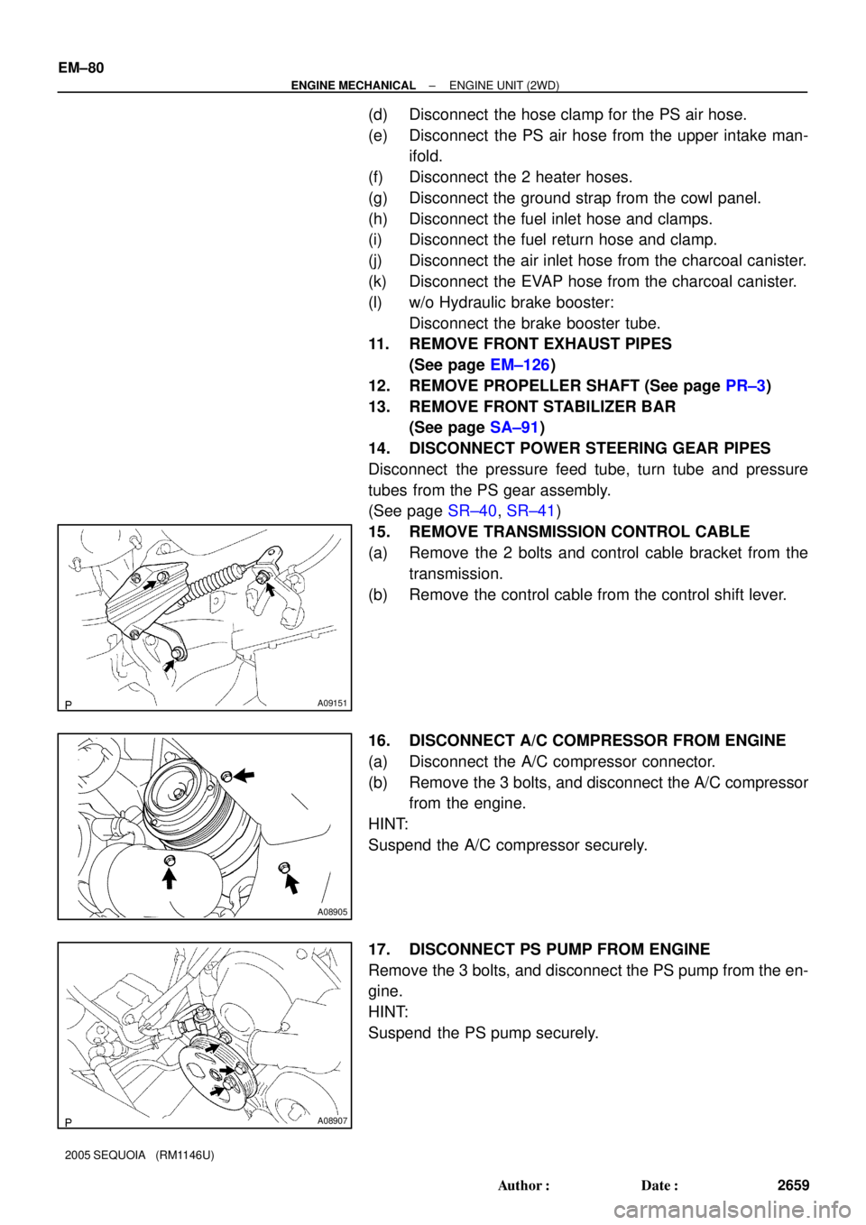
15. REMOVE TRANSMISSION CONTROL CABLE
(a) Remove the 2 bolts and control cable bracket from the
transmission.
(b) Remove the control cable from the control shift lever.
16. DISCONNECT A/C COMPRESSOR FROM ENGINE
(a) Disconnect the A/C compressor connector.
(b) Remove the 3 bolts, and disconnect the A/C compressor
from the engine.
HINT:
Suspend the A/C compressor securely.
17. DISCONNECT PS PUMP FROM ENGINE
Remove the 3 bolts, and disconnect the PS pump from the en-
gine.
HINT:
Suspend the PS pump securely.
Page 2673 of 4323
A08905
A09151
(a) EM±86
± ENGINE MECHANICALENGINE UNIT (2WD)
2665 Author�: Date�:
2005 SEQUOIA (RM1146U)
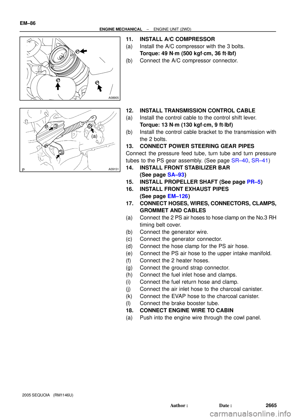
11. INSTALL A/C COMPRESSOR
(a) Install the A/C compressor with the 3 bolts.
Torque: 49 N´m (500 kgf´cm, 36 ft´lbf)
(b) Connect the A/C compressor connector.
12. INSTALL TRANSMISSION CONTROL CABLE
(a) Install the control cable to the control shift lever.
Torque: 13 N´m (130 kgf´cm, 9 ft´lbf)
(b) Install the control cable bracket to the transmission with
the 2 bolts.
13. CONNECT POWER STEERING GEAR PIPES
Connect the pressure feed tube, turn tube and turn pressure
tubes to the PS gear assembly. (See page SR±40, SR±41)
14. INSTALL FRONT STABILIZER BAR
(See page SA±93)
15. INSTALL PROPELLER SHAFT (See page PR±5)
16. INSTALL FRONT EXHAUST PIPES
(See page EM±126)
17. CONNECT HOSES, WIRES, CONNECTORS, CLAMPS,
GROMMET AND CABLES
(a) Connect the 2 PS air hoses to hose clamp on the No.3 RH
timing belt cover.
(b) Connect the generator wire.
(c) Connect the generator connector.
(d) Connect the hose clamp for the PS air hose.
(e) Connect the PS air hose to the upper intake manifold.
(f) Connect the 2 heater hoses.
(g) Connect the ground strap connector.
(h) Connect the fuel inlet hose and clamps.
(i) Connect the fuel return hose and clamp.
(j) Connect the air inlet hose to the charcoal canister.
(k) Connect the EVAP hose to the charcoal canister.
(l) Connect the brake booster tube.
18. CONNECT ENGINE WIRE TO CABIN
(a) Push into the engine wire through the cowl panel.
Page 2720 of 4323
EC089±06
B17455
Charcoal
Canister
VSV for EVAP
Air Injection
Control DriverTWC EVAP
Service
PortPurge Line VENT Line
ECM Fuel Tank
Air Filter
ECM To Intake Manifold
Pump Module
M
P
Pressure
Sensor Pump MotorVent ValveRefueling Valve
Air Inlet Line
MP
Air Switching
Valve
Air Switching
Valve No.2
VSVs Air PumpPressure
Sensor
EVAPORATIVE EMISSION (EVAP) CONTROL SYSTEM
SECONDARY AIR INJECTION SYSTEM EC±4
± EMISSION CONTROLPARTS LAYOUT AND SCHEMATIC DRAWING
2712 Author�: Date�:
2005 SEQUOIA (RM1146U)
DRAWING
Page 2727 of 4323
B06546
Pressure Gauge
Pressure
B17596
Fuel Tank Cap
Pressure
Gauge
B17662
Fuel Tank CapFuel Tank
Vent Line Hose
± EMISSION CONTROLEVAPORATIVE EMISSION (EVAP) CONTROL SYSTEM
EC±11
2719 Author�: Date�:
2005 SEQUOIA (RM1146U)
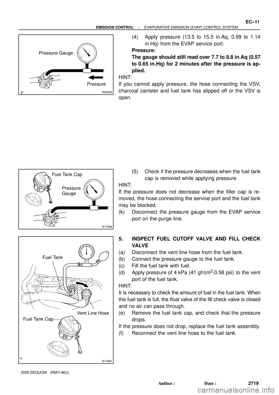
(4) Apply pressure (13.5 to 15.5 in.Aq, 0.99 to 1.14
in.Hq) from the EVAP service port.
Pressure:
The gauge should still read over 7.7 to 8.8 in.Aq (0.57
to 0.65 in.Hq) for 2 minutes after the pressure is ap-
plied.
HINT:
If you cannot apply pressure, the hose connecting the VSV,
charcoal canister and fuel tank has slipped off or the VSV is
open.
(5) Check if the pressure decreases when the fuel tank
cap is removed while applying pressure.
HINT:
If the pressure does not decrease when the filler cap is re-
moved, the hose connecting the service port and the fuel tank
may be blocked.
(k) Disconnect the pressure gauge from the EVAP service
port on the purge line.
5. INSPECT FUEL CUTOFF VALVE AND FILL CHECK
VA LV E
(a) Disconnect the vent line hose from the fuel tank.
(b) Connect the pressure gauge to the fuel tank.
(c) Fill the fuel tank with fuel.
(d) Apply pressure of 4 kPa (41 gf/cm
2,0.58 psi) to the vent
port of the fuel tank.
HINT:
It is necessary to check the amount of fuel in the fuel tank. When
the fuel tank is full, the float valve of the fill check valve is closed
and no air can pass through.
(e) Remove the fuel tank cap, and check that the pressure
drops.
If the pressure does not drop, replace the fuel tank assembly.
(f) Reconnect the vent line hose to the fuel tank.
Page 2744 of 4323
FI2553
SST
B16498
New Gasket
SF±2
± SFISFI SYSTEM
2736 Author�: Date�:
2005 SEQUOIA (RM1146U)
(b) When installing the battery, be especially careful to cor-
rectly connect the positive (+) and negative (±) cables.
(c) Do not give a severe impact to the SFI parts during remov-
al or installation. Handle all SFI parts carefully, especially
the ECM.
(d) Be careful during troubleshooting. Numerous transistor
circuits are used and even slight terminal contact can
cause further trouble.
(e) Do not open the ECM cover.
(f) When inspecting during rainy weather, take care to pre-
vent entry of water. Also, when washing the engine
compartment, prevent water from getting into the SFI
parts and wiring connectors.
(g) Parts should be replaced as an assembly.
(h) Care should be taken when pulling out and inserting wir-
ing connectors.
(1) Release the lock and pull out the connector, pulling
on the connectors.
(2) Fully insert the connector and check that it is locked.
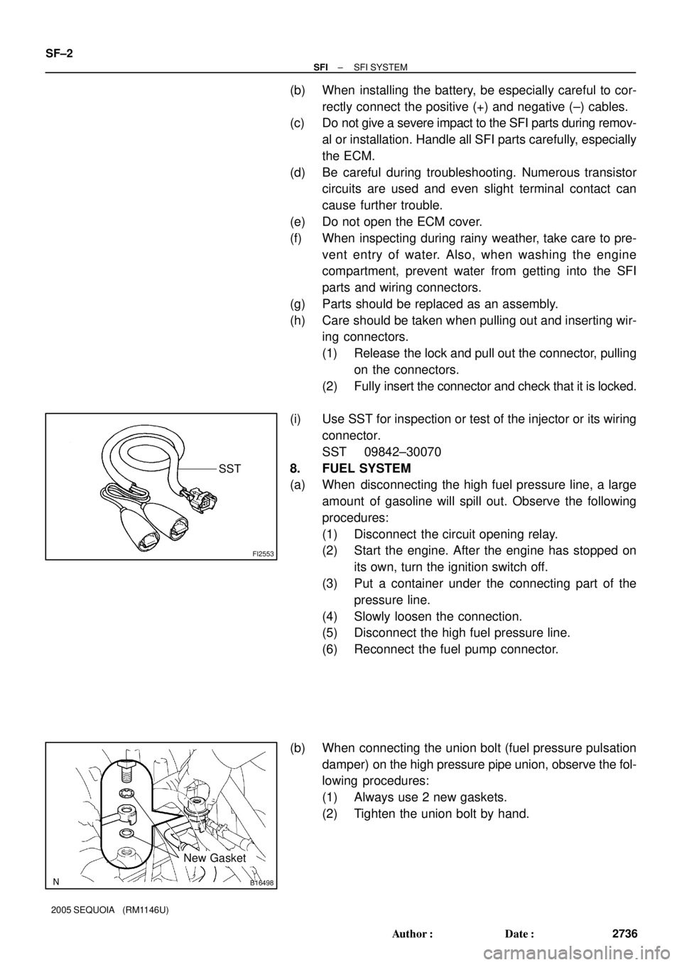
(i) Use SST for inspection or test of the injector or its wiring
connector.
SST 09842±30070
8. FUEL SYSTEM
(a) When disconnecting the high fuel pressure line, a large
amount of gasoline will spill out. Observe the following
procedures:
(1) Disconnect the circuit opening relay.
(2) Start the engine. After the engine has stopped on
its own, turn the ignition switch off.
(3) Put a container under the connecting part of the
pressure line.
(4) Slowly loosen the connection.
(5) Disconnect the high fuel pressure line.
(6) Reconnect the fuel pump connector.
(b) When connecting the union bolt (fuel pressure pulsation
damper) on the high pressure pipe union, observe the fol-
lowing procedures:
(1) Always use 2 new gaskets.
(2) Tighten the union bolt by hand.