Page 2685 of 4323
EM±98
± ENGINE MECHANICALENGINE UNIT (4WD)
2677 Author�: Date�:
2005 SEQUOIA (RM1146U)
22. PERFORM ROAD TEST
Check for abnormal noise, shock, slippage, correct shift points
and smooth operation.
23. RECHECK ENGINE COOLANT AND OIL LEVELS
Page 2686 of 4323
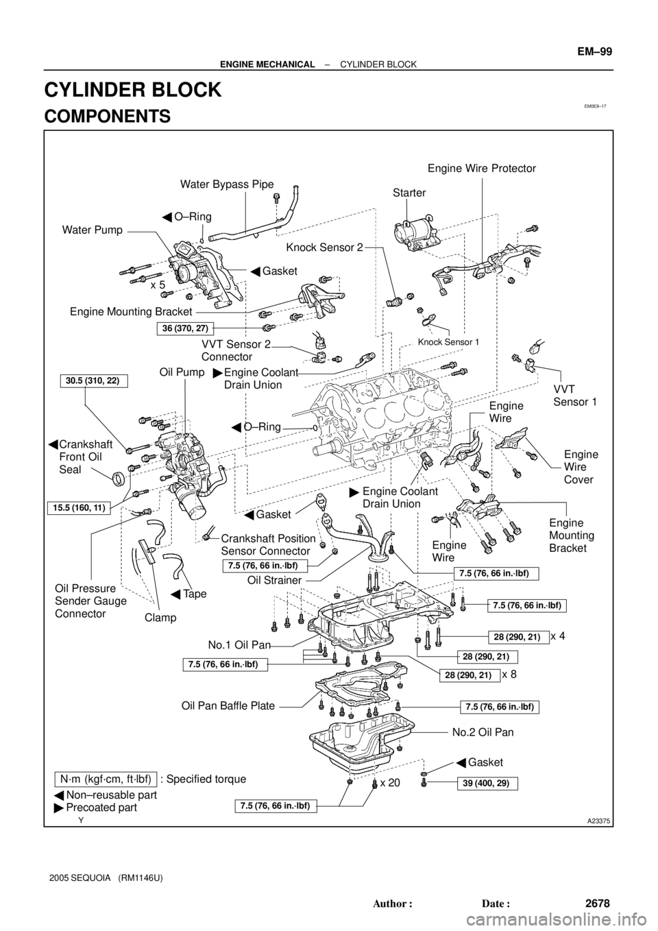
EM0E9±17
A23375
Engine Mounting Bracket
Oil Pump
Crankshaft
Front Oil
Seal
Crankshaft Position
Sensor Connector
No.1 Oil Pan
� Non±reusable part
� Precoated partOil StrainerEngine
Mounting
Bracket
VVT Sensor 2
ConnectorKnock Sensor 1
Knock Sensor 2
Engine Coolant
Drain UnionStarter
No.2 Oil Pan Oil Pan Baffle Platex 8 Water Pump
� Gasket � O±Ring
Engine
Wire
Engine
Wire
Cover VVT
Sensor 1
Engine Coolant
Drain Union
36 (370, 27)
30.5 (310, 22)
x 5
Oil Pressure
Sender Gauge
Connector
7.5 (76, 66 in.´lbf)
7.5 (76, 66 in.´lbf)
7.5 (76, 66 in.´lbf)
N´m (kgf´cm, ft´lbf) : Specified torque �
�
x 20
Clamp
Engine Wire Protector
� Tape
28 (290, 21)
7.5 (76, 66 in.´lbf)
28 (290, 21)
Water Bypass Pipe
7.5 (76, 66 in.´lbf)
� O±Ring
� Gasket
Engine
Wire
15.5 (160, 11)
39 (400, 29)
� Gasket
�
28 (290, 21)
7.5 (76, 66 in.´lbf)
x 4
± ENGINE MECHANICALCYLINDER BLOCK
EM±99
2678 Author�: Date�:
2005 SEQUOIA (RM1146U)
CYLINDER BLOCK
COMPONENTS
Page 2688 of 4323

DISASSEMBLY
1. INSTALL ENGINE TO ENGINE STAND
2. REMOVE")
EM122±05
A05112
Pull
Wire
Clamp
O±Ring
A08472
LH Side
± ENGINE MECHANICALCYLINDER BLOCK
EM±101
2680 Author�: Date�:
2005 SEQUOIA (RM1146U)
DISASSEMBLY
1. INSTALL ENGINE TO ENGINE STAND
2. REMOVE TIMING BELT AND PULLEYS
(See page EM±16)
3. REMOVE CYLINDER HEAD (See page EM±36)
4. REMOVE WATER BYPASS PIPE
(a) Disconnect the wire clamp (for knock sensor 1, 2) from
bracket of the water bypass pipe.
(b) Remove the bolt.
(c) Pull out the water bypass pipe from the water pump.
(d) Remove the O±ring from the water bypass pipe.
5. REMOVE STARTER (See page ST±5)
6. REMOVE KNOCK SENSORS (See page SF±66)
7. REMOVE VVT SENSORS (See page SF±77)
8. DISCONNECT ENGINE WIRE FROM LH SIDE OF CYL-
INDER BLOCK
(a) Remove the 2 bolts and engine wire cover from the LH
side of the cylinder block.
(b) Remove the 2 bolts, disconnect the brackets on the en-
gine wire from the cylinder block and engine mounting
bracket.
9. REMOVE OIL COOLER PIPE BRACKET FOR A/T
Remove the bolt and bracket.
10. REMOVE ENGINE MOUNTING BRACKETS
Remove the 4 bolts and mounting bracket. Remove the 2
mounting brackets.
11. REMOVE WATER PUMP (See page CO±6)
12. REMOVE NO.2 OIL PAN (See page LU±8)
13. REMOVE OIL PAN BAFFLE PLATE
14. REMOVE NO.1 OIL PAN (See page LU±8)
15. REMOVE OIL STRAINER
16. REMOVE OIL PUMP (See page LU±8)
17. REMOVE ENGINE COOLANT DRAIN UNIONS
Remove the 2 drain unions.
Page 2711 of 4323

14. INSTALL REAR OIL SEAL RETAINER
(")
A04848
Seal Width
3 ± 4 mm A
BA
B
A04855
New O±Ring
P12477
Seal Packing EM±124
± ENGINE MECHANICALCYLINDER BLOCK
2703 Author�: Date�:
2005 SEQUOIA (RM1146U)
14. INSTALL REAR OIL SEAL RETAINER
(a) Remove any old packing (FIPG) material and be careful
not to drop any oil on the contacting surfaces of the oil
seal retainer and cylinder block.
�Using a razor blade and gasket scraper, remove all
the old packing (FIPG) materials from the gasket
surfaces and sealing grooves.
�Thoroughly clean all components to remove all the
loose material.
�Using a non±residue solvent, clean both sealing
surfaces.
(b) Apply seal packing to the oil seal retainer as shown in the
illustration.
Seal packing: Part No. 08826±00080 or equivalent
�Install a nozzle that has been cut to a 3 ± 4 mm (0.12
± 0.16 in.) opening.
�Parts must be assembled within 5 minutes of ap-
plication. Otherwise the material must be removed
and reapplied.
�Immediately remove nozzle from the tube and rein-
stall cap.
(c) Install a new O±ring to the cylinder block.
(d) Install the oil seal retainer with the 7 bolts.
Torque: 8.0 N´m (80 kgf´cm, 71 in.´lbf)
15. INSTALL ENGINE COOLANT DRAIN UNIONS
(a) Apply seal packing to 2 or 3 threads.
Seal packing: Part No. 08826±00100 or equivalent
Page 2784 of 4323
SF0P5±16
B17470
B17469
SF±42
± SFITHROTTLE BODY
2776 Author�: Date�:
2005 SEQUOIA (RM1146U)
REMOVAL
1. REMOVE THROTTLE BODY COVER
2. DRAIN ENGINE COOLANT
3. REMOVE INTAKE AIR CONNECTOR
4. REMOVE THROTTLE BODY
(a) Disconnect the throttle control connector.
(b) Disconnect the 2 water bypass hoses from the throttle
body.
(c) Remove the nut and 3 bolts, and remove the throttle body
from the intake manifold.
Page 2785 of 4323
B17469
SF0P7±16
B17470
± SFITHROTTLE BODY
SF±43
2777 Author�: Date�:
2005 SEQUOIA (RM1146U)
INSTALLATION
1. INSTALL THROTTLE BODY
(a) Install the throttle body with the nut and 3 bolts.
Torque: 14 N´m (143 kgf´cm, 10 ft´lbf)
(b) Connect the 2 water bypass hoses to the throttle body.
(c) Connect the throttle control connector.
2. INSTALL INTAKE AIR CONNECTOR
3. FILL WITH ENGINE COOLANT (See page CO±2)
4. START ENGINE AND CHECK FOR ENGINE COOLANT
LEAKS
5. INSTALL THROTTLE BODY COVER
Page 2806 of 4323
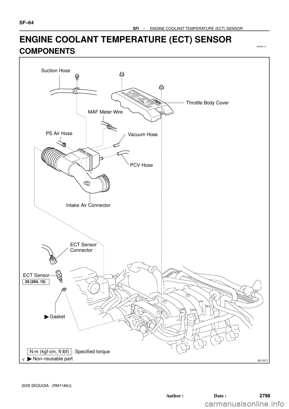
SF0PN±14
B17471
PS Air Hose
PCV Hose
Intake Air Connector
� GasketECT Sensor
Connector
ECT Sensor
N´m (kgf´cm, ft´lbf) : Specified torque
� Non±reusable part
Vacuum HoseThrottle Body Cover
MAF Meter Wire
Suction Hose
20 (204, 15)
SF±64
± SFIENGINE COOLANT TEMPERATURE (ECT) SENSOR
2798 Author�: Date�:
2005 SEQUOIA (RM1146U)
ENGINE COOLANT TEMPERATURE (ECT) SENSOR
COMPONENTS
Page 2807 of 4323
 Acceptable 30
20
10
5
3
2
1
0.5
0.3
0.2
0.1
40 ±20 0 20 60 80 100
(212) (176) (140) (104) (68) (32) (±4)
± SFIENGINE")
SF0PO±19
B02308
S01196S01699Z17274
Ohmmeter
Resistance kW
Temperature °C (°F) Acceptable 30
20
10
5
3
2
1
0.5
0.3
0.2
0.1
40 ±20 0 20 60 80 100
(212) (176) (140) (104) (68) (32) (±4)
± SFIENGINE COOLANT TEMPERATURE (ECT) SENSOR
SF±65
2799 Author�: Date�:
2005 SEQUOIA (RM1146U)
INSPECTION
1. DRAIN ENGINE COOLANT
2. REMOVE THROTTLE BODY COVER
3. REMOVE INTAKE AIR CONNECTOR
4. DISCONNECT THROTTLE BODY FROM INTAKE MAN-
IFOLDS
Remove the nut and 3 bolts, and disconnect the throttle body
from the intake manifold.
5. REMOVE ECT SENSOR
(a) Disconnect the ECT sensor connector.
(b) Remove the ECT sensor and gasket.
6. INSPECT ECT SENSOR
Using an ohmmeter, measure the resistance between the ter-
minals.
Resistance: Refer to the graph
If the resistance is not as specified, replace the ECT sensor.
7. REINSTALL ECT SENSOR
(a) Install a new gasket and the ECT sensor.
Torque: 19.6 N´m (200 kgf´cm, 14 ft´lbf)
(b) Connect the ECT sensor connector.
8. REINSTALL THROTTLE BODY TO INTAKE MAN-
IFOLDS
Install a new gasket and the throttle body with the 2 bolts and
2 nuts.
Torque: 20 N´m (204 kgf´cm, 15 ft´lbf)
9. REINSTALL INTAKE AIR CONNECTOR
10. REFILL WITH ENGINE COOLANT (See page CO±2)
11. REINSTALL THROTTLE BODY COVER