Page 2841 of 4323
CO0UV±03
B07219
± COOLINGRADIATOR
CO±17
2833 Author�: Date�:
2005 SEQUOIA (RM1146U)
REMOVAL
1. REMOVE ENGINE UNDER COVER
2. DRAIN ENGINE COOLANT
3. DISCONNECT RADIATOR RESERVOIR HOSE FROM
RADIATOR
4. DISCONNECT UPPER RADIATOR HOSE FROM RA-
DIATOR
5. DISCONNECT LOWER RADIATOR HOSE FROM RA-
DIATOR
6. DISCONNECT A/T OIL COOLER HOSES FROM RA-
DIATOR
7. REMOVE NO.2 FAN SHROUD
Remove the 2 clips and No.2 fan shroud.
8. REMOVE RADIATOR ASSEMBLY
Remove the 4 bolts and radiator assembly.
9. REMOVE NO.1 FAN SHROUD
Remove the 4 bolts and No.1 fan shroud.
Page 2842 of 4323
CO0UY±03
B07220
CO±18
± COOLINGRADIATOR
2834 Author�: Date�:
2005 SEQUOIA (RM1146U)
INSTALLATION
1. INSTALL NO.1 FAN SHROUD
Install the No.1 fan shroud with the 4 bolts.
Torque: 5.0 N´m (50 kgf´cm, 44 in.´lbf)
2. INSTALL RADIATOR ASSEMBLY
(a) Set the radiator bracket hooks to the radiator support
holes.
(b) Install the 4 bolts.
Torque: 12 N´m (120 N´m, 9 ft´lbf)
3. INSTALL NO.2 FAN SHROUD
Install the No.2 fan shroud with the 2 clips.
4. CONNECT A/T OIL COOLER HOSES TO RADIATOR
5. CONNECT UPPER RADIATOR HOSE TO RADIATOR
6. CONNECT LOWER RADIATOR HOSE TO RADIATOR
7. CONNECT RADIATOR RESERVOIR HOSE TO RADIA-
TOR
8. FILL WITH ENGINE COOLANT
9. START ENGINE AND CHECK FOR ENGINE COOLANT
LEAKS
10. RECHECK ENGINE COOLANT LEVEL
11. INSTALL ENGINE UNDER COVER
Page 2863 of 4323
LU08X-08
B07333
- LUBRICATIONOIL COOLER
LU-21
2855 Author�: Date�:
2005 SEQUOIA (RM1146U)
REMOVAL
1. DRAIN ENGINE COOLANT
2. REMOVE OIL FILTER (See page LU-2)
3. REMOVE OIL COOLER
(a) Disconnect the 2 oil cooler hoses from the oil cooler.
(b) Remove the union bolt, plate washer and oil cooler.
(c) Remove the O-ring from the oil cooler.
Page 2865 of 4323
LU08Z±10
B07332
New O±Ring
B07837
± LUBRICATIONOIL COOLER
LU±23
2857 Author�: Date�:
2005 SEQUOIA (RM1146U)
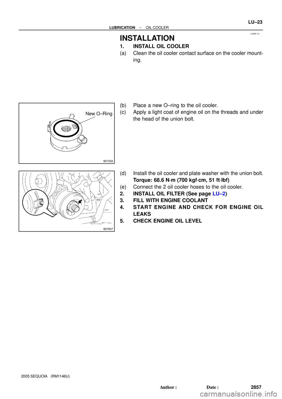
INSTALLATION
1. INSTALL OIL COOLER
(a) Clean the oil cooler contact surface on the cooler mount-
ing.
(b) Place a new O±ring to the oil cooler.
(c) Apply a light coat of engine oil on the threads and under
the head of the union bolt.
(d) Install the oil cooler and plate washer with the union bolt.
Torque: 68.6 N´m (700 kgf´cm, 51 ft´lbf)
(e) Connect the 2 oil cooler hoses to the oil cooler.
2. INSTALL OIL FILTER (See page LU±2)
3. FILL WITH ENGINE COOLANT
4. START ENGINE AND CHECK FOR ENGINE OIL
LEAKS
5. CHECK ENGINE OIL LEVEL
Page 2877 of 4323
IG08U±08
B17487
IG±8
± IGNITIONCAMSHAFT POSITION SENSOR
2869 Author�: Date�:
2005 SEQUOIA (RM1146U)
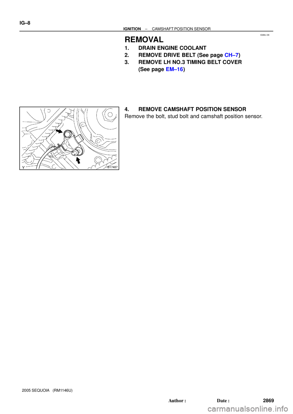
REMOVAL
1. DRAIN ENGINE COOLANT
2. REMOVE DRIVE BELT (See page CH±7)
3. REMOVE LH NO.3 TIMING BELT COVER
(See page EM±16)
4. REMOVE CAMSHAFT POSITION SENSOR
Remove the bolt, stud bolt and camshaft position sensor.
Page 2878 of 4323
IG08V±06
B17487
± IGNITIONCAMSHAFT POSITION SENSOR
IG±9
2870 Author�: Date�:
2005 SEQUOIA (RM1146U)
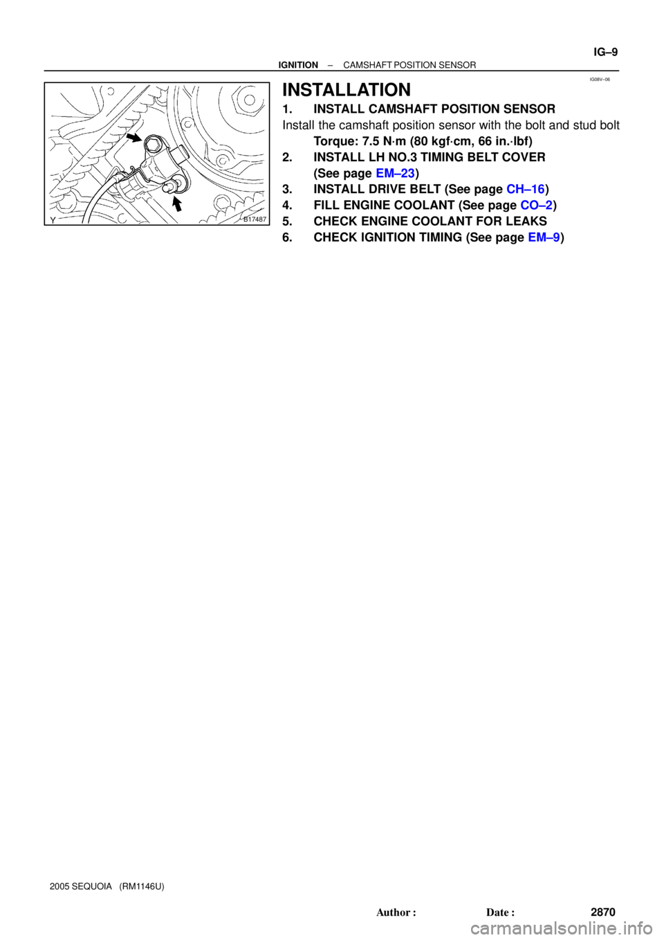
INSTALLATION
1. INSTALL CAMSHAFT POSITION SENSOR
Install the camshaft position sensor with the bolt and stud bolt
Torque: 7.5 N´m (80 kgf´cm, 66 in.´lbf)
2. INSTALL LH NO.3 TIMING BELT COVER
(See page EM±23)
3. INSTALL DRIVE BELT (See page CH±16)
4. FILL ENGINE COOLANT (See page CO±2)
5. CHECK ENGINE COOLANT FOR LEAKS
6. CHECK IGNITION TIMING (See page EM±9)
Page 3468 of 4323
(3.4W) Fuel Gauge
Z05730
Warning Light
Ignition
Switch
Battery
1
23
45
Wire
Harness Side:
I28772
I01278
BE±56
± BODY ELECTRICALCOMBINATION METER
346")
I21530
Ignition
Switch
Battery(Wire Harness Side)(3.4W) Fuel Gauge
Z05730
Warning Light
Ignition
Switch
Battery
1
23
45
Wire
Harness Side:
I28772
I01278
BE±56
± BODY ELECTRICALCOMBINATION METER
3460 Author�: Date�:
2005 SEQUOIA (RM1146U)
(c) Connect terminals 2 and 3 on the wire harness side con-
nector through a 3.4 watts test bulb.
(d) Turn the ignition switch ON, check that the bulb comes on
and the receiver gauge needle moves towards the full
side.
HINT:
Because of silicon oil in the gauge, it will take a short time for
the needle to stabilize.
If operation is not as specified, inspect the receiver gauge resis-
tance.
4. INSPECT FUEL LEVEL WARNING LIGHT OPERATION
(a) Disconnect the connector from the sender gauge.
(b) Connect terminals 2 and 3 on the wire harness side con-
nector.
(c) Turn the ignition switch ON and check that the warning
light comes on.
If the warning light does not come on, test the bulb or inspect
the wire harness.
5. INSPECT ENGINE COOLANT TEMPERATURE SEND-
ER GAUGE RESISTANCE
(a) Disconnect the engine coolant temperature sender
gauge.
(b) Measure the resistance between terminals 1 and 2 of the
connector according to the value(s) in the table below.
Temperature °C (°F)Resistance (W)
±20 (±4)13,840 to 16,330
20 (68)2,320 to 2,590
80 (176)310 to 326
110 (230)139.9 to 143.5
If resistance value is not as specified, replace the engine cool-
ant sender gauge.
6. INSPECT OIL PRESSURE SENDER OPERATION
(a) Disconnect the connector from the oil pressure sender.
(b) Check that no continuity exists between terminal and
ground with the engine stopped.
(c) Check that continuity exists between terminal and ground
with the engine running.
HINT:
Oil pressure should be over 24.5 kPa (0.25 kgf/cm
2, 3.55 psi).
If operation is not as specified, replace the oil pressure sender.
Page 3768 of 4323

AC3H3±02
I11129
I11197
Water Hose
Heater Radiator
PipeUpper
LH
RH
45 ± 10°
Lower
Hose Clip
Second RidgeLH
RH
I11130
± AIR CONDITIONINGHEATER UNIT
AC±33
3760 Author�: Date�:
2005 SEQUOIA (RM1146U)
REMOVAL
1. REMOVE COOLING UNIT (See page AC±26)
2. DRAIN ENGINE COOLANT FROM RADIATOR
HINT:
It is not necessary to drain out all the coolant.
3. DISCONNECT WATER VALVE CONTROL CABLE
FROM WATER VALVE (See page AC±79)
4. DISCONNECT WATER HOSES FROM HEATER RA-
DIATOR PIPES
(a) Using pliers, grip the claws of the clips and slide the clips
along the hose.
(b) Disconnect the water hoses.
(c) Remove the grommet.
HINT:
At the time of installation, refer to the following:
�Push the water hose onto the heater radiator pipe up to
the second ridge on the pipe.
�Install the hose clip to the position shown in the illustra-
tion.
5. REMOVE INSTRUMENT PANEL AND REINFORCE-
MENT (See page BO±89)
6. REMOVE DEFROSTER NOZZLE AND HEATER TO
REGISTER DUCT
7. REMOVE HEATER UNIT
Remove the 3 screws and heater unit.