Page 1704 of 4323
DIDDX±01
I28733
Instrument Panel J/B
� ECU±IG Fuse
� PWR SEAT Fuse
Power Seat Motor (Reclining) Lumbar Support Control Motor
Seat Memory Switch
Power Seat Motor (Rear Lifter)
Lumbar Support Control Switch
Position Control ECU & Switch Assy
Power Seat Motor (Front Vertical)Power Seat Motor (Slide)
DI±1502± DIAGNOSTICSPOWER SEAT CONTROL SYSTEM (w/ Driving Position
Memory)
1696 Author�: Date�:
2005 SEQUOIA (RM1146U)
LOCATION
Page 1705 of 4323
DIDDZ±01
I28552
Position Control ECU
& Switch Assy
Park/Neutral
Position Switch
Combination
MeterPower Seat Motor
Driver Side (Reclining)
Power Seat Motor
Driver Side (Slide) Power Seat Motor
Driver Side (Front Vertical) Power Seat Motor
Driver Side (Lifter)
Front Door Courtesy
Light Switch Assy Seat Memory Switch Lumbar
Support
Control
MotorLumbar Support
Control Switch To Battery
To Battery To Ignition SwitchECU±B
PWR SEATECU±IGSYSB
IG
+BRCL+
RCL±
LFT+
LFT±
FRV+
FRV±
SLD+
SLD±
SW1
SW2
MMRYDCTY
Key Unlock
Warning Switch
KSW
Body ECU
BEANTo Ignition Switch
± DIAGNOSTICSPOWER SEAT CONTROL SYSTEM (w/ Driving Position
Memory)DI±1503
1697 Author�: Date�:
2005 SEQUOIA (RM1146U)
SYSTEM DIAGRAM
Page 1709 of 4323
DIDE2±01
Inspector 's Name:
Customer 's Name
Date Vehicle
Brought InProduction Date VIN
Licence Plate No.
Odometer Reading/ /
/ /
Date Problem First Occurred
Frequency Problem Occurs/ /
ConstantIntermittent ( times a day)
km
miles
All functions do not operate.
Weather Conditions
When Problem
OccurredWeather
Outdoor
TemperatureOnly onceFine
Various/Others
CloudyRainySnowy
Hot
Cold ( �C ( �F))
WarmCool
Problem Symptoms
Sliding function does not operate.
Reclining function does not operate.
Front vertical function does not operate.
Lifter function does not operate.
Seat position memory function does not operate.
Others
POWER SEAT CONTROL SYSTEM Check Sheet
Lumbar support function does not operate.
± DIAGNOSTICSPOWER SEAT CONTROL SYSTEM (w/ Driving Position
Memory)DI±1507
1701 Author�: Date�:
2005 SEQUOIA (RM1146U)
CUSTOMER PROBLEM ANALYSIS CHECK
Page 1710 of 4323

DIDE4±01
DI±1508± DIAGNOSTICSPOWER SEAT CONTROL SYSTEM (w/ Driving Position
Memory)
1702 Author�: Date�:
2005 SEQUOIA (RM1146U)
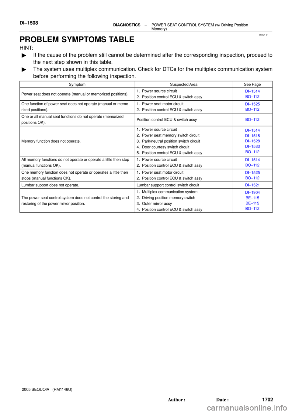
PROBLEM SYMPTOMS TABLE
HINT:
�If the cause of the problem still cannot be determined after the corresponding inspection, proceed to
the next step shown in this table.
�The system uses multiplex communication. Check for DTCs for the multiplex communication system
before performing the following inspection.
SymptomSuspected AreaSee Page
Power seat does not operate (manual or memorized positions).1. Power source circuit
2. Position control ECU & switch assyDI±1514
BO±112
One function of power seat does not operate (manual or memo-
rized positions).1. Power seat motor circuit
2. Position control ECU & switch assyDI±1525
BO±112
One or all manual seat functions do not operate (memorized
positions OK).Position control ECU & switch assyBO±112
Memory function does not operate.
1. Power source circuit
2. Power seat memory switch circuit
3. Park/neutral position switch circuit
4. Door courtesy switch circuit
5. Position control ECU & switch assyDI±1514
DI±1518
DI±1528
DI±1533
BO±112
All memory functions do not operate or operate a little then stop
(manual functions OK).1. Power source circuit
2. Position control ECU & switch assyDI±1514
BO±112
One memory function does not operate or operates a little then
stops (manual functions OK).1. Power seat motor circuit
2. Position control ECU & switch assyDI±1525
BO±112
Lumbar support does not operate.Lumbar support control switch circuitDI±1521
The power seat control system does not control the storing and
restoring of the power mirror position.
1. Multiplex communication system
2. Driving position memory switch
3. Outer mirror assy
4. Position control ECU & switch assyDI±1904
BE±115
BE±115
BO±112
Page 1723 of 4323
I28448
PWR SEAT Instrument Panel J/B
ALT 161
1 2L±O L±O
BI29L4
Lumbar Support Control
Switch (Driver's Seat)
3 1 2
4
5 Rear Front
W
W±B W±B
BH BatteryLR1 L A
A
BI2 1G
1L
F10
FL BlockJ24 J/C
L3
Lumbar Support
Control Motor L±O
J24 J/C J/C
L±O
J31 J323
R B
H
B58C
G
BBB 2
W±B W±BE2E
± DIAGNOSTICSPOWER SEAT CONTROL SYSTEM (w/ Driving Position
Memory)DI±1521
1715 Author�: Date�:
2005 SEQUOIA (RM1146U)
Lumbar support control switch circuit
CIRCUIT DESCRIPTION
The lumbar support control switch that controls lumbar support is connected to the lumbar support control
motor via a wire harness. This circuit can freely operate regardless of the condition of the ECU.
WIRING DIAGRAM
DIDE9±01
Page 1724 of 4323
I28700
HOLD (Front)RELEASE (Rear)
DI±1522± DIAGNOSTICSPOWER SEAT CONTROL SYSTEM (w/ Driving Position
Memory)
1716 Author�: Date�:
2005 SEQUOIA (RM1146U)
INSPECTION PROCEDURE
1 Check fuse (PWR SEAT).
PREPARATION:
Remove the PWR SEAT fuse from the instrument panel J/B.
CHECK:
Measure the resistance.
OK:
Below 1 W
NG Replace fuse.
OK
2 Inspect lumbar support control switch.
PREPARATION:
Disconnect the lumbar support control switch connector.
CHECK:
Measure the resistance of each terminal, as shown in the il-
lustration and table.
OK:
Tester ConnectionSwitch PositionSpecified Condition
1 ± 2HOLD (Front)Below 1 W
3 ± 4HOLD (Front)Below 1 W
1 ± 2OFFBelow 1 W
4 ± 5OFFBelow 1 W
1 ± 3RELEASE (Rear)Below 1 W
4 ± 5RELEASE (Rear)Below 1 W
NG Replace lumbar support control switch assy
(See page BO±112).
OK
Page 1725 of 4323

I28701
Wire Harness Side:
Lumbar Support Control Switch
L4
I28702
Lumbar Support Control Motor
Clockwise
Counter-
clockwise
Driving AxisL3
± DIAGNOSTICSPOWER SEAT CONTROL SYSTEM (w/ Driving Position
Memory)DI±1523
1717 Author�: Date�:
2005 SEQUOIA (RM1146U)
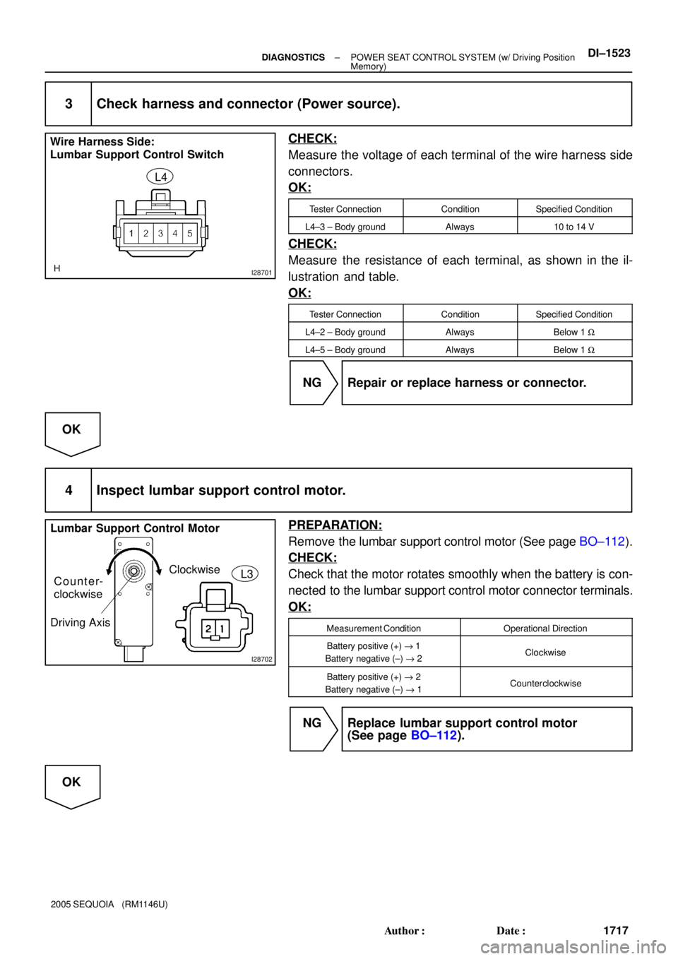
3 Check harness and connector (Power source).
CHECK:
Measure the voltage of each terminal of the wire harness side
connectors.
OK:
Tester ConnectionConditionSpecified Condition
L4±3 ± Body groundAlways10 to 14 V
CHECK:
Measure the resistance of each terminal, as shown in the il-
lustration and table.
OK:
Tester ConnectionConditionSpecified Condition
L4±2 ± Body groundAlwaysBelow 1 W
L4±5 ± Body groundAlwaysBelow 1 W
NG Repair or replace harness or connector.
OK
4 Inspect lumbar support control motor.
PREPARATION:
Remove the lumbar support control motor (See page BO±112).
CHECK:
Check that the motor rotates smoothly when the battery is con-
nected to the lumbar support control motor connector terminals.
OK:
Measurement ConditionOperational Direction
Battery positive (+) "1
Battery negative (±) " 2Clockwise
Battery positive (+) " 2
Battery negative (±) " 1Counterclockwise
NG Replace lumbar support control motor
(See page BO±112).
OK
Page 1726 of 4323
I28701
Wire Harness Side:
Lumbar Support Control Switch
L4
I28555
Wire Harness Side:
Lumbar Support
Control MotorL3
DI±1524± DIAGNOSTICSPOWER SEAT CONTROL SYSTEM (w/ Driving Position
Memory)
1718 Author�: Date�:
2005 SEQUOIA (RM1146U)
5 Check harness and connector (Lumbar support control switch ± lumbar support
control motor).
CHECK:
Measure the resistance of each terminal, as shown in the il-
lustration and table.
OK:
Tester ConnectionConditionSpecified Condition
L4±1 ± L3±2AlwaysBelow 1 W
L4±4 ± L3±1AlwaysBelow 1 W
L4±1 ± Body groundAlways10 kW or higher
L4±4 ± Body groundAlways10 kW or higher
NG Repair or replace harness or connector.
OK
Proceed to next circuit inspection shown in
problem symptoms table (See page
DI±1508).