Page 3336 of 4323
RS0T9±06
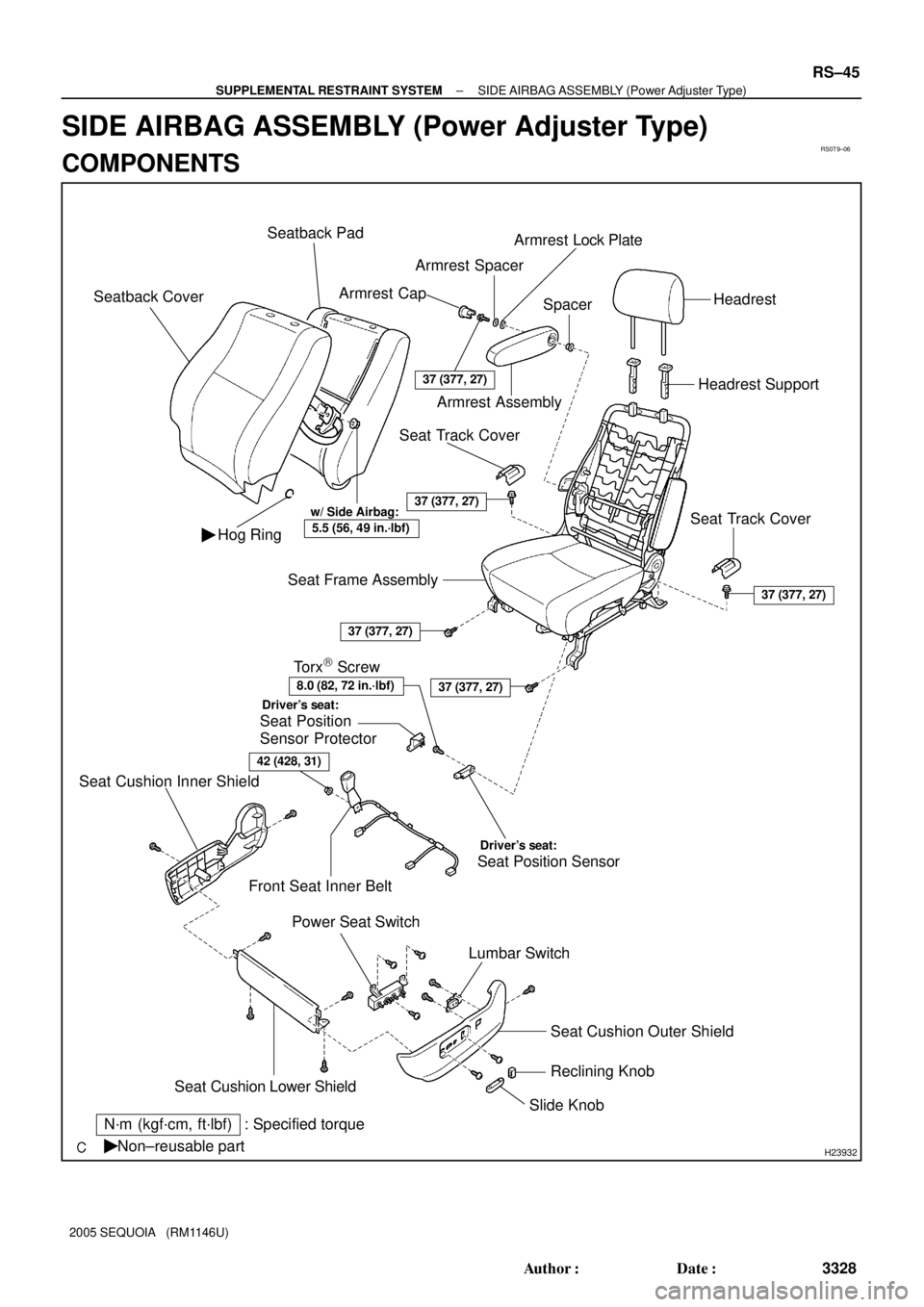
H23932
37 (377, 27)
37 (377, 27)
37 (377, 27)
37 (377, 27)
37 (377, 27)
42 (428, 31)
N´m (kgf´cm, ft´lbf) : Specified torque
Non±reusable part �Seat Cushion Outer Shield
Slide KnobReclining Knob Lumbar Switch Power Seat Switch
Seat Cushion Lower ShieldSeat Position Sensor Seat Cushion Inner Shield
Driver's seat:
Torx) Screw
Seat Position
Sensor Protector
Driver's seat:
Hog Ring �
Front Seat Inner BeltHeadrest Support
Seat Frame Assembly Seatback CoverSeatback Pad
Spacer
Seat Track Cover Seat Track CoverArmrest Assembly Armrest CapArmrest SpacerArmrest Lock Plate
Headrest
8.0 (82, 72 in.´lbf)
w/ Side Airbag:
5.5 (56, 49 in.´lbf)
± SUPPLEMENTAL RESTRAINT SYSTEMSIDE AIRBAG ASSEMBLY (Power Adjuster Type)
RS±45
3328 Author�: Date�:
2005 SEQUOIA (RM1146U)
SIDE AIRBAG ASSEMBLY (Power Adjuster Type)
COMPONENTS
Page 3423 of 4323
 ºReclining Operationº does not operate.
1. Power Seat Switch (D, P)
2. Reclining Motor (D, P)
3. Wire HarnessBE")
± BODY ELECTRICALTROUBLESHOOTING
BE±11
3415 Author�: Date�:
2005 SEQUOIA (RM1146U) ºReclining Operationº does not operate.
1. Power Seat Switch (D, P)
2. Reclining Motor (D, P)
3. Wire HarnessBE±109
BE±109
±
ºLumbar Support Operationº does not operate.
1. Power Seat Switch (D)
2. Lumbar Support Motor (D)
3. Wire HarnessBE±109
BE±109
±
(D): Driver's Seat
(P): Passenger's Seat
POWER SEAT CONTROL SYSTEM (w/ Driving Position Memory)
This system uses the multiplex communication system, so check diagnosis system of the multiplex commu-
nication system before you proceed with troubleshooting.
SymptomSuspected AreaSee Page
Power seat control system abnormal operation.See DIAGNOSIS SYSTEMDI±1505
POWER MIRROR CONTROL SYSTEM (w/o Driving Position Memory)
This system uses the multiplex communication system, so check diagnosis system of the multiplex commu-
nication system before you proceed with troubleshooting.
SymptomSuspect AreaSee page
Mirror does not operate.1. Mirror Switch
2. Wire HarnessBE±115
±
Mirror operates abnormally.
1. Mirror Switch
2. Mirror Motor
3. Wire HarnessBE±115
BE±115
±
POWER MIRROR CONTROL SYSTEM (w/ Driving Position Memory)
SymptomSuspect AreaSee page
Remote control mirror LH only does not operate.
(w/ Driving position memory)1. Remote control mirror motor LH circuit
2. Remote control mirror position sensor LH circuit
3. Driver door ECUDI±1808
DI±1810
±
Remote control mirror RH only does not operate.
(w/ Driving position memory)1. Remote control mirror motor RH circuit
2. Remote control mirror position sensor RH circuit
3. Passenger door ECUDI±1845
DI±1847
±
ELECTRO CHROMIC MIRROR SYSTEM
SymptomSuspect AreaSee page
Electro Chromic Inner Mirror does not operate.
1. ECU±IG Fuse
2. Electro Chromic Inner Mirror
3. Wire HarnessBE±14
BE±122
±
SEAT HEATER SYSTEM
SymptomSuspect AreaSee page
Seat heaters do not operate.
(Driver's and Passenger's)
1. SEAT HTR Fuse
2. Seat Heater Switch (D, P)
3. Seat Heater
4. Wire HarnessBE±14
BE±124
BE±124
±
Driver's seat heater does not operate.1. Seat Heater Switch (D, P)
2. Wire HarnessBE±124
±
Passenger's seat heater does not operate.1. Seat Heater Switch (D, P)
2. Wire HarnessBE±124
±
Seat heater temperature is too hot.Seat HeaterBE±124
AUDIO SYSTEM
SymptomSuspect AreaSee page
Audio system abnormal operation.See DIAGNOSIS SYSTEMDI±1962
Page 3520 of 4323
BE17F±08
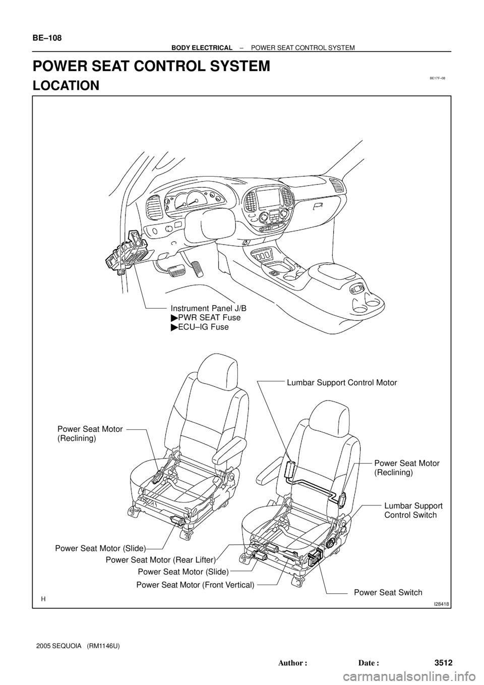
I28418
Instrument Panel J/B
� PWR SEAT Fuse
� ECU±IG Fuse
Power Seat Motor
(Reclining)Lumbar Support Control Motor
Power Seat Motor (Slide)
Power Seat Motor (Slide)
Power Seat Motor (Front Vertical) Power Seat Motor (Rear Lifter)
Power Seat SwitchPower Seat Motor
(Reclining)
Lumbar Support
Control Switch
BE±108
± BODY ELECTRICALPOWER SEAT CONTROL SYSTEM
3512 Author�: Date�:
2005 SEQUOIA (RM1146U)
POWER SEAT CONTROL SYSTEM
LOCATION
Page 3522 of 4323

(b)
2
1
1 2
I11936
21
I11937
21
I07254
(a)
(b)
21
1 2
BE±110
± BODY ELECTRICALPOWER SEAT CONTROL SYSTEM
3514 Author�: Date�:
2005 SEQUOIA (RM1146U)
3. INSPECT DRIV")
I27710
ForwardRelease
I07253
(a)
(b)
2
1
1 2
I11936
21
I11937
21
I07254
(a)
(b)
21
1 2
BE±110
± BODY ELECTRICALPOWER SEAT CONTROL SYSTEM
3514 Author�: Date�:
2005 SEQUOIA (RM1146U)
3. INSPECT DRIVER'S LUMBAR SUPPORT CONTROL
SWITCH CONTINUITY
Switch positionTester connectionSpecified condition
Forward1 ± 2, 3 ± 4Continuity
OFF1 ± 2, 4 ± 5Continuity
Release1 ± 3, 4 ± 5Continuity
If continuity is not as specified, replace the switch.
4. INSPECT SLIDE MOTOR OPERATION
(a) Connect the positive (+) lead from the battery to terminal
1 and the negative (±) lead to terminal 2, check that the
motor turns clockwise.
(b) Reverse the polarity, check that the motor turns counter-
clockwise.
If operation is not as specified, replace the seat adjuster.
5. INSPECT SLIDE MOTOR PTC THERMISTOR OPERA-
TION
( ): Passenger Side
(a) Connect the positive (+) lead from the battery to terminal
2 (1), the positive (+) lead from the ammeter to terminal
1 (2) and the negative (±) lead to the battery negative (±)
terminal, then move the seat cushion to the rear position.
(b) Continue to apply voltage, check that current changes to
less than 1 ampere within 4 to 90 seconds.
(c) Disconnect the leads from terminals.
(d) Approximately 60 seconds later, connect the positive (+)
lead from the battery to terminal 1 (2) and the negative (±)
lead to terminal 2 (1), check that the seat cushion begins
to move forwards.
If operation is not as specified, replace the seat adjuster.
6. INSPECT FRONT TILT MOTOR OPERATION
(a) Connect the positive (+) lead from the battery to terminal
1 and the negative (±) lead to terminal 2, check that the
motor turns clockwise.
(b) Reverse the polarity, check that the motor turns counter-
clockwise.
If operation is not as specified, replace the seat adjuster.
Page 3524 of 4323

(b)
21
1 2
N21868
21
N21869
21
I04163
21
I05473
21
BE±112
± BODY ELECTRICALPOWER SEAT CONTROL SYSTEM
3516 Author�: Date�:
2005 SEQUOIA (RM1146U)
10. INSPECT RECLINING MOTOR OPERATION
(a")
I07256
(a)
(b)
21
1 2
N21868
21
N21869
21
I04163
21
I05473
21
BE±112
± BODY ELECTRICALPOWER SEAT CONTROL SYSTEM
3516 Author�: Date�:
2005 SEQUOIA (RM1146U)
10. INSPECT RECLINING MOTOR OPERATION
(a) Connect the positive (+) lead from the battery to terminal
1 and the negative (±) lead to terminal 2, check that the
motor turns clockwise.
(b) Reverse the polarity, check that the motor turns counter-
clockwise.
If operation is not as specified, replace the seat adjuster.
11. INSPECT RECLINING MOTOR PTC THERMISTOR OP-
ERATION
(a) Connect the positive (+) lead from the battery to terminal
2, the positive (+) lead from the ammeter to terminal 1 and
the negative (±) lead to the battery negative (±) terminal,
then recline the seat back to the most forward position.
(b) Continue to apply voltage, check that the current changes
to less than 1 ampere within 4 to 90 seconds.
(c) Disconnect the leads from the terminals.
(d) Approximately 60 seconds later, connect the positive (+)
lead from the battery to terminal 1 and the negative (±)
lead to terminal 2, check that the seat back begins to fall
backward.
If operation is not as specified, replace the seat adjuster.
12. INSPECT LUMBAR SUPPORT MOTOR OPERATION
(a) Connect the positive (+) lead from the battery to terminal
1 and the negative (±) lead to terminal 2, check that the
lumbar support moves to release side.
(b) Reverse the polarity, check that the lumbar support
moves forward.
If operation is not as specified, replace the seat adjuster.
Page 3525 of 4323
I04165
21
I04166
21
± BODY ELECTRICALPOWER SEAT CONTROL SYSTEM
BE±113
3517 Author�: Date�:
2005 SEQUOIA (RM1146U)
13. INSPECT LUMBAR SUPPORT MOTOR PTC THERM-
ISTOR OPERATION
(a) Connect the positive (+) lead from the battery to terminal
2 and the negative (±) lead to terminal 1 on the lumbar
support motor connector and move the lumbar support to
front end position.
(b) Continue to apply voltage, check that a circuit breaker op-
eration noise can be heard within 4 to 60 seconds.
(c) Reverse the polarity, check that the lumbar support be-
gins to move to release side within approximately 60 se-
conds.
If operation is not as specified, replace the motor.
Page 3671 of 4323

37 (380, 27)
37 (380, 27)
37 (380, 27)
37 (380, 27)
42 (430, 32) Seatback Cover
Seat Cushion
Cover
Seat Cushion
PadArmrest CapArmrest Spacer
Armrest
Lock Plate
Spacer
Arm")
BO4S6±01
H24329
37 (380, 27)
37 (380, 27)
37 (380, 27)
37 (380, 27)
37 (380, 27)
42 (430, 32) Seatback Cover
Seat Cushion
Cover
Seat Cushion
PadArmrest CapArmrest Spacer
Armrest
Lock Plate
Spacer
Armrest
AssemblyHeadrest
Headrest Support Seatback Pad
Lumbar Support
Adjuster
Seat Frame Assembly Seat Position Sensor
Protector
Seat Position
Sensor
Seat Cushion
Inner Shield
Seat Cushion
Lower ShieldFront Seat Inner BeltRH Reclining
Adjuster Inside
CoverRH Seatback
ShieldVertical Adjuster
Bracket Inner Cover
Vertical Adjuster
Bracket Outer Cover
LH Reclining
Adjuster Inside Cover
Reclining Knob
Slide Knob
Seat Cushion Outer ShieldLumbar Switch Power Seat SwitchLH Seatback Shield
�Hog RingSeat Track
Cover
Seat Track
CoverBushing
�Hog Ring
Non±reusable part: Specified torque
N´m (kgf´cm, ft´lbf)
�
w/ Side airbag:
5.5 (56, 49 in.´lbf)
w/ Seat heater:
w/ Seat heater:
Seat Cushion Heater Assembly
Seatback
Heater Assembly
Occupant Classification ECUPassenger's seat:
Driver's seat:
Driver's seat:
BO±110
± BODYFRONT SEAT (Power Adjuster Type)
3663 Author�: Date�:
2005 SEQUOIA (RM1146U)
FRONT SEAT (Power Adjuster Type)
COMPONENTS
HINT:
The procedures listed below are for the LH side.
Page 3673 of 4323
BO4S8±01
H24311
H24312
H24313
BO±112
± BODYFRONT SEAT (Power Adjuster Type)
3665 Author�: Date�:
2005 SEQUOIA (RM1146U)
DISASSEMBLY
CAUTION:
Wear safety gloves, because the sharp edges and surfaces
of the seat frame may cause injury to the hands.
HINT:
�The procedures listed below are for the LH side.
�Tape the screwdriver tip before using it to remove the
parts.
�For easy removal of the lumbar support adjuster, release
the lumbar support through lumbar switch operation.
1. REMOVE HEADREST
2. REMOVE SLIDE KNOB AND RECLINING KNOB
Using a screwdriver, remove the slide knob and reclining knob.
HINT:
Tape the screwdriver tip before use.
3. REMOVE SEAT CUSHION LOWER SHIELD, SEAT
CUSHION OUTER SHIELD AND SEAT CUSHION IN-
NER SHIELD
(a) Remove the screw from the seat cushion outer shield.
(b) Perform the same procedure on the seat cushion inner
shield.
(c) Remove the 2 screws from the seat cushion outer shield.
(d) Remove the screw from the seat cushion inner shield.