Page 1205 of 1943

AB0119H10689H10656
ON
Tc
(+) (±)
AB0117 AB0119H01302H12918
LOCK
ON
Airbag Sensor Assembly
Tc
± DIAGNOSTICSSUPPLEMENTAL RESTRAINT SYSTEM
DI±643
2001 PRIUS (RM778U)
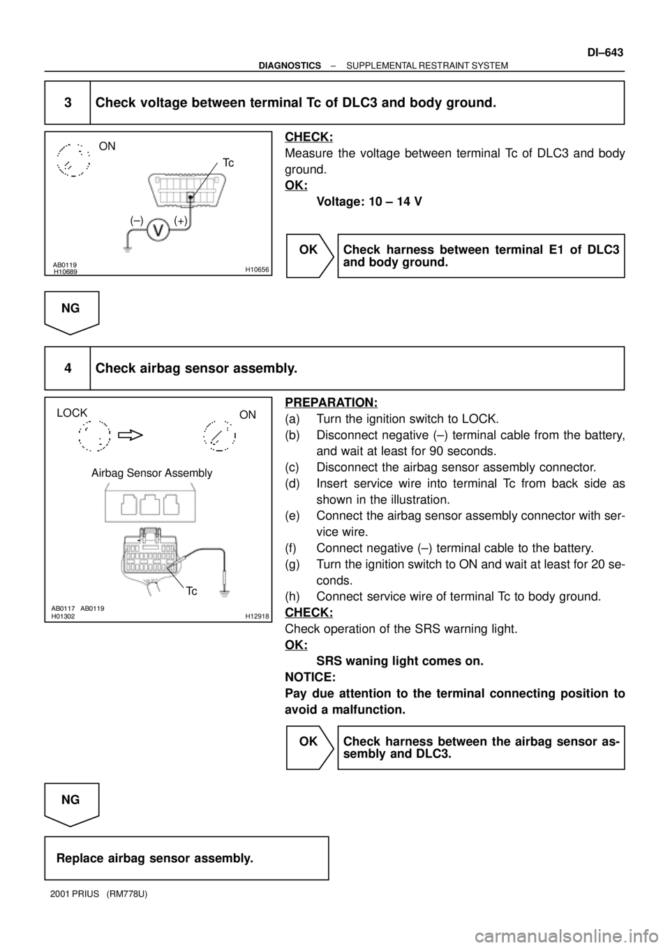
3 Check voltage between terminal Tc of DLC3 and body ground.
CHECK:
Measure the voltage between terminal Tc of DLC3 and body
ground.
OK:
Voltage: 10 ± 14 V
OK Check harness between terminal E1 of DLC3
and body ground.
NG
4 Check airbag sensor assembly.
PREPARATION:
(a) Turn the ignition switch to LOCK.
(b) Disconnect negative (±) terminal cable from the battery,
and wait at least for 90 seconds.
(c) Disconnect the airbag sensor assembly connector.
(d) Insert service wire into terminal Tc from back side as
shown in the illustration.
(e) Connect the airbag sensor assembly connector with ser-
vice wire.
(f) Connect negative (±) terminal cable to the battery.
(g) Turn the ignition switch to ON and wait at least for 20 se-
conds.
(h) Connect service wire of terminal Tc to body ground.
CHECK:
Check operation of the SRS warning light.
OK:
SRS waning light comes on.
NOTICE:
Pay due attention to the terminal connecting position to
avoid a malfunction.
OK Check harness between the airbag sensor as-
sembly and DLC3.
NG
Replace airbag sensor assembly.
Page 1210 of 1943

DI±654
± DIAGNOSTICSCRUISE CONTROL SYSTEM
2001 PRIUS (RM778U)
CIRCUIT INSPECTION
DTC P1520 Stop light switch circuit
CIRCUIT DESCRIPTION
When the brake pedal is depressed, the stop light switch sends a signal to the hybrid vehicle control ECU.
When the hybrid vehicle control ECU receives this signal, it cancels the cruise control.
A fail±safe function is provided so that the cancel functions normally, even if there is a malfunction in the stop
light signal circuit.
The cancel condition is that battery voltage is supplied to terminal STP.
When the brake is on, battery voltage is normally applied through the STOP fuse and stop light switch to
terminal STP of the hybrid vehicle control ECU, and the hybrid vehicle control ECU turns the cruise control
OFF.
If the harness connected to terminal STP has an open circuit, terminal STP will have battery voltage and
the cruise control will be turned OFF.
DTC No.Detection ItemTrouble Area
P1520Stop light switch circuit.
�Stop light switch
�Harness or connector between hybrid vehicle control ECU
and stop light switch circuit
�Hybrid vehicle control ECU
DI7NI±01
Page 1211 of 1943
I15477
Instrument Panel J/B
FL Block No. 2S3
Stop Light SW I15
Ignition SW
Engine Room J/BHybrid Vehicle
Control ECU
J25 ID1B±Y
ST1± IG2 AM2
1G±W
2
R±B2
H14
STP 1
H14 B±W
34
6 B±W
J24
B C B±W W±R
7
6
2
2C
15A AM21
2GW±R
9
1J 2
1B B
1
F12B±G
120A MAIN
Battery1
F13
1
F18J15
D J14
E G±W
Instrument Panel J/B
9
2K15A STOP
W
100A DC/DC
F11 1
2H
FL Block No. 1
1
F131
B±GS3
Stop Light SW J/C
J/C
FL Block No. 1
± DIAGNOSTICSCRUISE CONTROL SYSTEM
DI±655
2001 PRIUS (RM778U)
WIRING DIAGRAM
Page 1212 of 1943
I19096
ON
STP
(+) (±)
DI±656
± DIAGNOSTICSCRUISE CONTROL SYSTEM
2001 PRIUS (RM778U)
INSPECTION PROCEDURE
1 Check operation of stop light.
CHECK:
Check that stop light comes on when brake pedal is depressed, and turns off when brake pedal is released.
NG Check stop light system (See page BE±2).
OK
2 Check voltage between terminal STP of hybrid vehicle control ECU connector
and body ground.
PREPARATION:
(a) Remove the hybrid vehicle control ECU with connectors
still connected.
(b) Turn ignition switch ON.
CHECK:
Measure voltage between terminal STP of hybrid vehicle con-
trol ECU connector and body ground, when the brake pedal is
depressed and released.
OK:
Depressed10 ± 14 V
ReleasedBelow 1 V
OK Proceed to next circuit inspection shown in
problem symptom table (See page DI±648).
NG
Page 1213 of 1943
I19096
ON
ST1±
(+) (±)
± DIAGNOSTICSCRUISE CONTROL SYSTEM
DI±657
2001 PRIUS (RM778U)
3 Check voltage between terminal ST1± of hybrid vehicle control ECU connector
and body ground.
PREPARATION:
(a) Remove the hybrid vehicle control ECU with connectors
still connected.
(b) Turn ignition switch ON.
CHECK:
Measure voltage between terminal ST1± of hybrid vehicle con-
trol ECU connector and body ground, when the brake pedal is
depressed and released.
OK:
DepressedBelow 1 V
Released10 ± 14 V
OK Proceed to next circuit inspection shown in
problem symptoms table (See page DI±648).
NG
4 Check wire harness and connector between terminal STP of hybrid vehicle con-
trol ECU and stop light switch, and terminal ST1± of hybrid vehicle control ECU
and stop light switch (See page IN±41).
NG Repair or replace harness or connector.
OK
Check and replace hybrid vehicle control
ECU (See page DI±174
).
Page 1216 of 1943
I15479
Combination Meter
FL Block No. 1Instrument Panel J/B
to Body ECU 5A AM1IG1
Relay
3
GR±B14
C10
2A
CRUISE 8
W±B
B±G22
C10 L
2K8
2
C11
W±B I15 Ignition SW
AM1
IG1
F11
Battery
ID 10A GAUGE
5
AJ11
J/C 2 1 2B6
2B3
2D6 W
W±G
B±Y
24
B±Y
1F13
1F18
1FL Block No. 2
120A MAIN
100A DC/DC7
2A
1
2H
IH BR
± DIAGNOSTICSCRUISE CONTROL SYSTEM
DI±665
2001 PRIUS (RM778U)
CRUISE MAIN Indicator Light Circuit
CIRCUIT DESCRIPTION
When the cruise control main switch is turned ON, CRUISE MAIN indicator light lights up.
WIRING DIAGRAM
DI7NL±01
Page 1220 of 1943

DI7XR±01
I17803
Connector ºAº Connector ºBº
(LHD model) COMBINATION METER DI±672
± DIAGNOSTICSCOMBINATION METER SYSTEM
2001 PRIUS (RM778U)
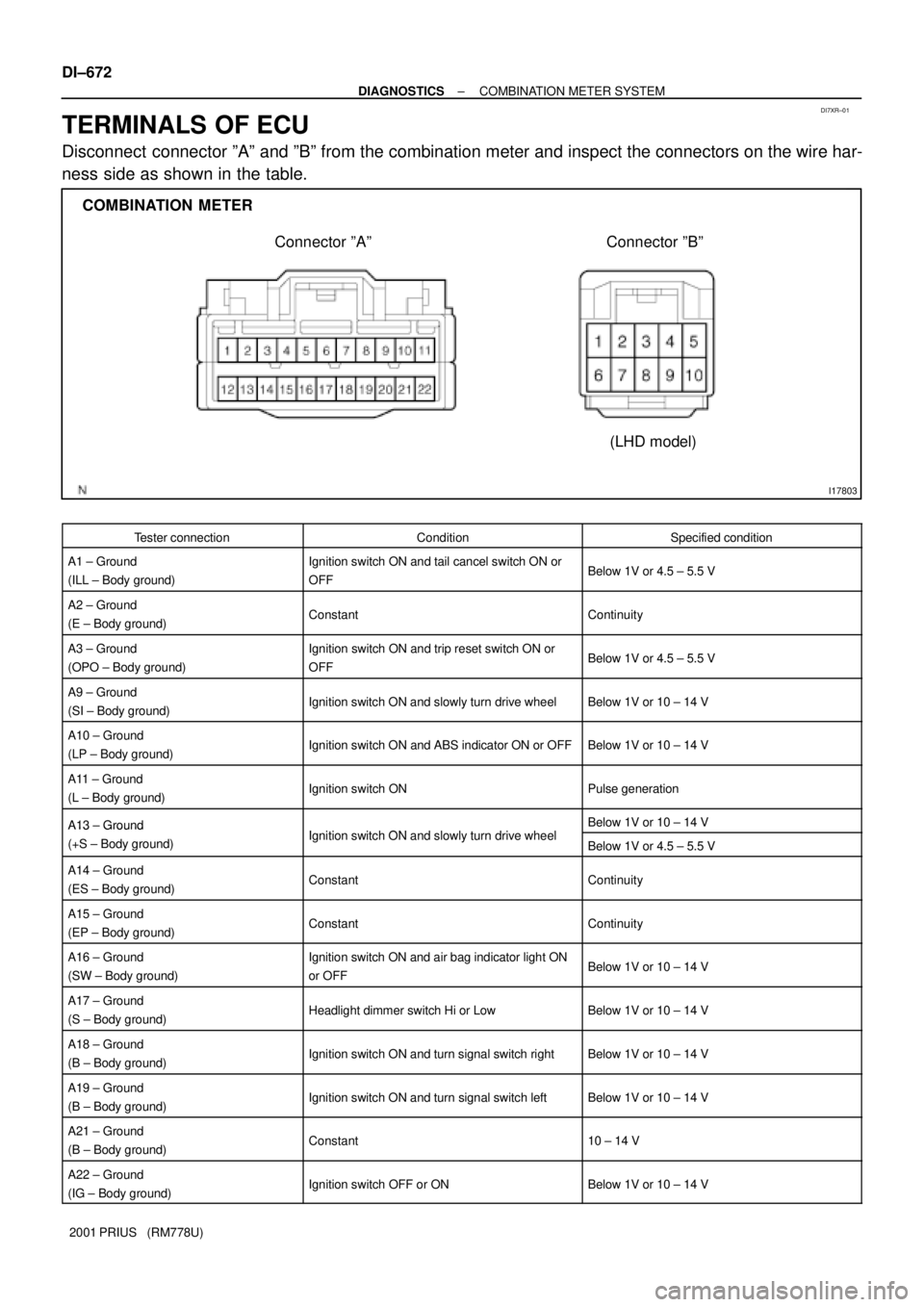
TERMINALS OF ECU
Disconnect connector ºAº and ºBº from the combination meter and inspect the connectors on the wire har-
ness side as shown in the table.
Tester connectionConditionSpecified condition
A1 ± Ground
(ILL ± Body ground)Ignition switch ON and tail cancel switch ON or
OFFBelow 1V or 4.5 ± 5.5 V
A2 ± Ground
(E ± Body ground)ConstantContinuity
A3 ± Ground
(OPO ± Body ground)Ignition switch ON and trip reset switch ON or
OFFBelow 1V or 4.5 ± 5.5 V
A9 ± Ground
(SI ± Body ground)Ignition switch ON and slowly turn drive wheelBelow 1V or 10 ± 14 V
A10 ± Ground
(LP ± Body ground)Ignition switch ON and ABS indicator ON or OFFBelow 1V or 10 ± 14 V
A11 ± Ground
(L ± Body ground)Ignition switch ONPulse generation
A13 ± GroundI iti it h ON d l l t d i h lBelow 1V or 10 ± 14 VA13 Ground
(+S ± Body ground)Ignition switch ON and slowly turn drive wheelBelow 1V or 4.5 ± 5.5 V
A14 ± Ground
(ES ± Body ground)ConstantContinuity
A15 ± Ground
(EP ± Body ground)ConstantContinuity
A16 ± Ground
(SW ± Body ground)Ignition switch ON and air bag indicator light ON
or OFFBelow 1V or 10 ± 14 V
A17 ± Ground
(S ± Body ground)Headlight dimmer switch Hi or LowBelow 1V or 10 ± 14 V
A18 ± Ground
(B ± Body ground)Ignition switch ON and turn signal switch rightBelow 1V or 10 ± 14 V
A19 ± Ground
(B ± Body ground)Ignition switch ON and turn signal switch leftBelow 1V or 10 ± 14 V
A21 ± Ground
(B ± Body ground)Constant10 ± 14 V
A22 ± Ground
(IG ± Body ground)Ignition switch OFF or ONBelow 1V or 10 ± 14 V
Page 1222 of 1943

DI7XS±01
DI±674
± DIAGNOSTICSCOMBINATION METER SYSTEM
2001 PRIUS (RM778U)
PROBLEM SYMPTOMS TABLE
TROUBLESHOOTING:
Flow chart No.SymptomSee page
1Check the communication between the combination meter and the multiplex com-
munication circuit.DI±671
2The whole meter does not functionDI±672
3The margin of error in speedometer is large. Or it remains as 0 mph.DI±673
4Fuel receiver gauge is inoperative or improper.DI±674
5Indicators or warning lights do not light up.DI±676
Fuel gauge:
SymptomSuspect AreaSee page
Displayed level is higher or lower than the actual level.1. Inclination sensor resetting
2. Body ECUBE±47
IN±41
General:
SymptomSuspect area
Meter display does not properly function.3. Combination meter ECU
Entirely black screen appears.1. Fuse
2. Wire harness and connector
3. Combination meter ECU
Turning the light control switch ON does not dim the light.1. Illumination switch
2. Wire harness and connector
3. Combination meter ECU
Brightness cannot be changed by the illumination switch operation.1. Illumination switch
2. Wire harness and connector
3. Combination meter ECU
Speedometer:
SymptomSuspect area
Improper display (Remained as 0 km/h)1. Accessory that utilizes vehicle speed signals
2. Brake ECU
3. Combination meter ECU
4. Wire harness and connector
Speedometer only does not light up.1. Combination meter ECU
Abnormal display (Incomplete numbers displayed)1. Combination meter ECU
DIsplayed value changes frequently or sharply.1. Accessory that utilizes vehicle speed signals
2. Brake ECU
3. Combination meter ECU
4. Wire harness and connector
Margin of error in speedometer is large.1. Accessory that utilizes vehicle speed signals
2. Brake ECU
3. Combination meter ECU
4. Wire harness and connector
ODO/TRIP Meter:
SymptomSuspect area
ODO/TRIP only does not light up.1. Combination meter ECU
Abnormal display (Incomplete number displayed)1. Combination meter ECU
Both meters do not integrate values. (When speedometer is normal)1. Combination meter ECU
Trip meter only does not integrate values.1. ODO/TRIP switch
2. Combination meter ECU