Page 380 of 1943

CHASSIS ± BRAKES
Battery
Acceptance
Capacity
182CH58
Braking
Force
Regenerative
Braking ForceHydraulic
Braking Force
Vehicle SpeedRegenerative
Braking ForceHydraulic
Braking Force
Time
Changes in Regenerative Braking Force Changes in Braking Force Apportionment
Braking
Force
Driver's DemandDriver's Demand 11 8
2) Regenerative Brake Cooperative Control
a. General
The regenerative brake cooperative control uses the switching valves and linear solenoid valves to regu-
late the hydraulic pressure that is supplied to the wheel cylinders. It also operates cooperatively with
the regenerative braking force that is generated in the MG2 in accordance with the master cylinder pres-
sure.
b. Apportioning of the Brake Force
The apportioning of the brake force between the hydraulic brake and the regenerative brake varies by
the vehicle speed and time.
The apportioning of the brake force between the hydraulic brake and the regenerative brake is con-
trolled so that the total brake force of the hydraulic brake and the regenerative brake matches the brake
force that the driver requires.
� Imagery Drawing �
c. Operation
Regenerative brake cooperative control is executed when the vehicle is driven in the shift position ªDº
or ªBº.
The master cylinder pressure that is generated when the driver presses on the brake pedal is detected
by the pressure sensor, and the brake ECU calculates the brake force request factor. A portion of the
brake force request factor is transmitted to the HV ECU in the form of a regenerative brake activation
request factor. The HV ECU executes generative braking by commanding the electric motor to generate
negative torque.
The brake ECU controls the opening of the linear solenoid valves, which are used for increasing / de-
creasing the hydraulic pressure, to regulate the wheel cylinder hydraulic pressure in relation to the mas-
ter cylinder hydraulic pressure, thus compensating for the brake force that is not provided sufficiently
by the regenerative brake.
While the regenerative brake cooperative control is being prohibited due to an abnormality in the sys-
tem, or when the shift lever is in a position other than D or B, the regenerative braking force is not gener-
ated. At this time, only the hydraulic braking force is applied by turning ON (opening) the linear sole-
noid valve SLA and turning OFF (closing) the SLR.
Page 453 of 1943

APPENDIX
5
10
15
20
25
30
35
40
45
50
55
60
65
70
Area
Item
Major Dimensions & Vehicle Weights Performance Engine Engine
Chassis
Electrical
192
MAJOR TECHNICAL SPECIFICATIONS
U.S.A. and CanadaBody Type4-Door SedanVehicle GradeÐModel CodeNHW11L-AEEEBANHW11L-AEEEBKLength mm (in.)4305 (169.5)u
OverallWidth mm (in.)1695 (66.7)uOverallHeight mm (in.)1465 (57.6)uWheel Base mm (in.)2550 (100.4)u
TreadFront mm (in.)1475 (58.1)uTreadRear mm (in.)1480 (58.3)u
Effective Head RoomFront mm (in.)985 (38.8)uEffective Head RoomRear mm (in.)942 (37.1)u
Effective Leg RoomFront mm (in.)1047 (41.2)uEffective Leg RoomRear mm (in.)899 (35.4)u
Shoulder RoomFront mm (in.)1342 (52.8)uShoulder RoomRear mm (in.)1325 (52.2)u
OverhangFront mm (in.)815 (32.1)uOverhangRear mm (in.)940 (37.0)uMin. Running Ground Clearance mm (in.)125 (4.9)uAngle of Approach degrees145uAngle of Departure degrees225uFront kg (lb)770 (1700)u
Curb WeightRear kg (lb)485 (1065)uCurb WeightTotal kg (lb)1255 (1765)uFront kg (lb)890 (1965)u
Gross Vehicle WeightRear kg (lb)750 (1650)uGross Vehicle WeightTotal kg (lb)1640 (3615)uFuel Tank Capacity� (US. gal., lmp.gal.)45* (11.9, 9.9)uLuggage Compartment Capacity m3 (cu.ft.)0.39 (137.7)uMax. Speed km/h (mph)160 (99.4)uMax. Cruising Speed km/h (mph)160 (99.4)u
Acceleration0 to 100 km/h sec.12.7uAcceleration0 to 400 m sec.19.0u1st Gear km/h (mph)ÐÐ
Max. Permissible2nd Gear km/h (mph)ÐÐMax. Permissible
Speed3rd Gear km/h (mph)ÐÐp
4th Gear km/h (mph)ÐÐ
Min. Turning RadiusWall to Wall m (ft.)10.2 (33.5)uMin. Turning Radius
(Outside Front)Curb to Curb m (ft.)9.4 (30.8)uEngine Type1NZ-FXEuValve Mechanism16-Valve, DOHCuBore y Stroke mm (in.)75.0 y 84.7 (2.95 y 3.33)uDisplacement cm3 (cu.in.)1497 (91.4)uCompression Ratio13.0uCarburetor TypeSFIuResearch Octane No. RON95uMax. Output (EEC) kW/rpm (HP@rpm)52/4500 (70@4500)uMax. Torque (EEC) N´m/rpm (lb-ft@rpm)111/4200 (82@4200)uBattery Capacity (5HR) Voltage & Amp. Hr.12 ± 28uAlternator Output WattsÐÐStarter Output kWÐÐClutch TypeÐÐTransaxle TypeP111uIn FirstÐÐIn SecondÐÐ
Transmission GearIn ThirdÐÐTransmission Gear
RatioIn FourthÐÐIn FifthÐÐIn ReverseÐÐCounter Gear RatioÐÐDifferential Gear Ratio (Final)3.905u
Brake TypeFrontVentilated DiscuBrake TypeRearL.T. DrumuParking Brake TypeL.T. DrumuBrake Booster Type and Size in.HydraulicuProportioning Valve TypeP-Valveu
Suspension TypeFrontMacPherson StrutuSuspension TypeRearTorsion Beanu
Stabilizer BarFrontSTDuStabilizer BarRearSTDuSteering Gear TypeRack and PinionuSteering Gear Ratio (Overall)16.4~18.3uPower Steering TypeElectric Motoru
*: EPA / CARB ORVR Test conditions
Page 1821 of 1943

I12020
I12021
BE±84
± BODY ELECTRICALWIRELESS DOOR LOCK CONTROL SYSTEM
2001 PRIUS (RM778U)
2. CHECK BATTERY CAPACITY
HINT:
�Make sure to use the TOYOTA electrical tester.
�With the battery unloaded, judge can not be made wheth-
er the battery is available or not on the test.
�When the transmitter is faulty, the energy amount left in
the battery might not be checked correctly.
�On the lithium battery used for the transmitter, the voltage
more than 2.5 V with the battery unloaded is shown on the
tester until the energy is completely consumed.
Accordingly when inspecting the energy amount left in the
battery, it is necessary to measure the voltage when the
battery is loaded. (1.2 kW).
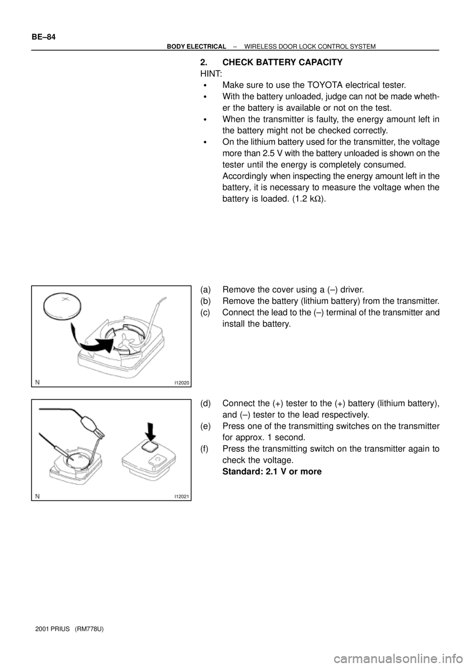
(a) Remove the cover using a (±) driver.
(b) Remove the battery (lithium battery) from the transmitter.
(c) Connect the lead to the (±) terminal of the transmitter and
install the battery.
(d) Connect the (+) tester to the (+) battery (lithium battery),
and (±) tester to the lead respectively.
(e) Press one of the transmitting switches on the transmitter
for approx. 1 second.
(f) Press the transmitting switch on the transmitter again to
check the voltage.
Standard: 2.1 V or more