Page 601 of 1943

SS13W±06
SS±26
± SERVICE SPECIFICATIONSSUSPENSION AND AXLE
148 Author�: Date�:
2001 PRIUS (RM778U)
SUSPENSION AND AXLE
SERVICE DATA
Cold tire inflation
pressureTire size: P175/65R14 84S Front
Rear240 kPa (2.4 kgf/cm2, 35 psi)
230 kPa (2.3 kgf/cm2, 33 psi)
Vehicle height
P175/65R14Front*1
Rear*2191 mm (7.52 in.)
239 mm (9.41 in.)
Camber
Right±left error±0°26' ± 45' (±0.43° ± 0.75°)
45' (0.75°) or less
Front wheel
Caster
Right±left error1°02' ± 45' (1.03° ± 0.75°)
45' (0.75°) or less
Front wheel
alignmentSteering axis inclination
Right±left error9°52' ± 45' (9.87° ± 0.75°)
45' (0.75°) or less
Toe±in (total)
Rack end length difference0°06' ± 12' (0.1° ± 0.2°, 1 ± 2 mm, 0.04± 0.08 in.)
1.5 mm (0.059 in.) or less
Wheel angle
Inside wheel
Outside wheel: Reference
42°42' ± 2° (42.70° ± 2°)
35°54' (35.90°)
Rear wheel
Camber
Right±left error±1°30' ± 45' (±0.93° ± 0.75°)
45' (0.75°) or less
Rear wheel
alignmentToe±in (total)0°06' ± 20' (0.1° ± 0.33°)
1 ± 3.0 mm (0.04 ± 0.12 in.)
FtlAxle bearing backlash Maximum0.05 mm (0.0020 in.)Front axleAxle hub deviationMaximum0.07 mm (0.0028 in.)
Front drive shaftDrive shaft standard length LH
RH579.9 ± 5.0 mm (22.831 ± 0.197 in.)
836.9 ± 5.0 mm (32.949 ± 0.197 in.)
Ft iLower suspension arm ball joint turning torque1.0 ± 4.9 N´m (10 ± 50 kgf´cm, 8.7 ± 43 in.´lbf)Front suspensionStabilizer bar link ball joint turning torque0.05 ± 1.0 N´m (0.5 ± 10 kgf´cm, 0.4 ± 8.7 in.´lbf)
RlAxle bearing backlash Maximum0.05 mm (0.0020 in.)Rear axleAxle hub deviationMaximum0.07 mm (0.0028 in.)
*1: Front measuring point
Measure the distance from the ground to the head center of the front side lower suspension arm mounting
bolt.
*2: Rear measuring point
Measure the distance from the ground to the center of the rear axle beam mounting bolt.
Page 1654 of 1943

SA0CC±10
R03031
R15157
Front
R07928
R14731
Backlash:Deviation: SA±2
± SUSPENSION AND AXLETIRE AND WHEEL
1452 Author�: Date�:
2001 PRIUS (RM778U)
TIRE AND WHEEL
INSPECTION
1. INSPECT TIRE
(a) Check the tires for wear and proper inflation pressure.
Cold tire inflation pressure:
(Tire size: P175/65R14 84S)
FrontRear
240 kPa (2.4 kgf/cm2, 35 psi)230 kPa (2.3 kgf/cm2, 33 psi)
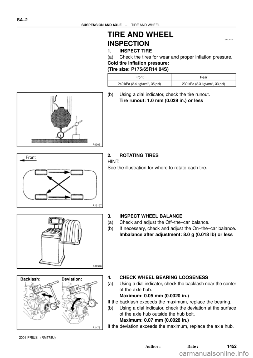
(b) Using a dial indicator, check the tire runout.
Tire runout: 1.0 mm (0.039 in.) or less
2. ROTATING TIRES
HINT:
See the illustration for where to rotate each tire.
3. INSPECT WHEEL BALANCE
(a) Check and adjust the Off±the±car balance.
(b) If necessary, check and adjust the On±the±car balance.
Imbalance after adjustment: 8.0 g (0.018 lb) or less
4. CHECK WHEEL BEARING LOOSENESS
(a) Using a dial indicator, check the backlash near the center
of the axle hub.
Maximum: 0.05 mm (0.0020 in.)
If the backlash exceeds the maximum, replace the bearing.
(b) Using a dial indicator, check the deviation at the surface
of the axle hub outside the hub bolt.
Maximum: 0.07 mm (0.0028 in.)
If the deviation exceeds the maximum, replace the axle hub.
Page 1726 of 1943

Z14034
Fig.1
Fig.2Power Source
Safing
Sensor
Squibs
Deceleration Sensor
H01581
Outer
H01582
Lock of connector is released
Disconnection is completed
± SUPPLEMENTAL RESTRAINT SYSTEMSRS AIRBAG
RS±7
2001 PRIUS (RM778U)
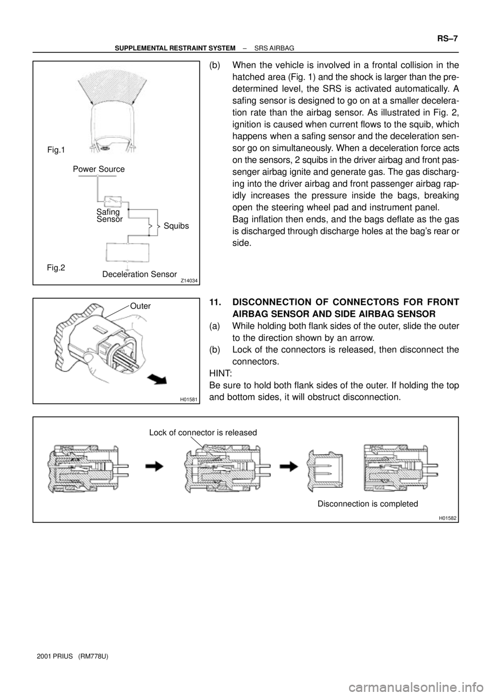
(b) When the vehicle is involved in a frontal collision in the
hatched area (Fig. 1) and the shock is larger than the pre-
determined level, the SRS is activated automatically. A
safing sensor is designed to go on at a smaller decelera-
tion rate than the airbag sensor. As illustrated in Fig. 2,
ignition is caused when current flows to the squib, which
happens when a safing sensor and the deceleration sen-
sor go on simultaneously. When a deceleration force acts
on the sensors, 2 squibs in the driver airbag and front pas-
senger airbag ignite and generate gas. The gas discharg-
ing into the driver airbag and front passenger airbag rap-
idly increases the pressure inside the bags, breaking
open the steering wheel pad and instrument panel.
Bag inflation then ends, and the bags deflate as the gas
is discharged through discharge holes at the bag's rear or
side.
11. DISCONNECTION OF CONNECTORS FOR FRONT
AIRBAG SENSOR AND SIDE AIRBAG SENSOR
(a) While holding both flank sides of the outer, slide the outer
to the direction shown by an arrow.
(b) Lock of the connectors is released, then disconnect the
connectors.
HINT:
Be sure to hold both flank sides of the outer. If holding the top
and bottom sides, it will obstruct disconnection.
Page 1776 of 1943

I17791
0.4 °
3 m (9.84 ft) H 29.7 mm
(1.17 in.)
7
V RH Line
W90 °
V LH Line4
Low Beam:
V LH LineV Line V RH Line 65
6
29.7 mm
(1.17 in.)
High Beam:
V LH LineV Line V RH Line 6
5629.7 mm
(1.17 in.)
29.7 mm
(1.17 in.) H 4
O: step No.
7
H4
W
W
± BODY ELECTRICALHEADLIGHT AND TAILLIGHT SYSTEM
BE±23
2001 PRIUS (RM778U)
ADJUST HEADLIGHT AIM ONLY
(a) Place the vehicle in the following conditions.
�The area around the headlight is not deformed.
�The vehicle is parked on a level surface.
�Tire inflation pressure is the specified value.
�A driver is in the driver's seat and the vehicle is in
a state ready for driving (with a tank full).
�The vehicle has been bounced several times.
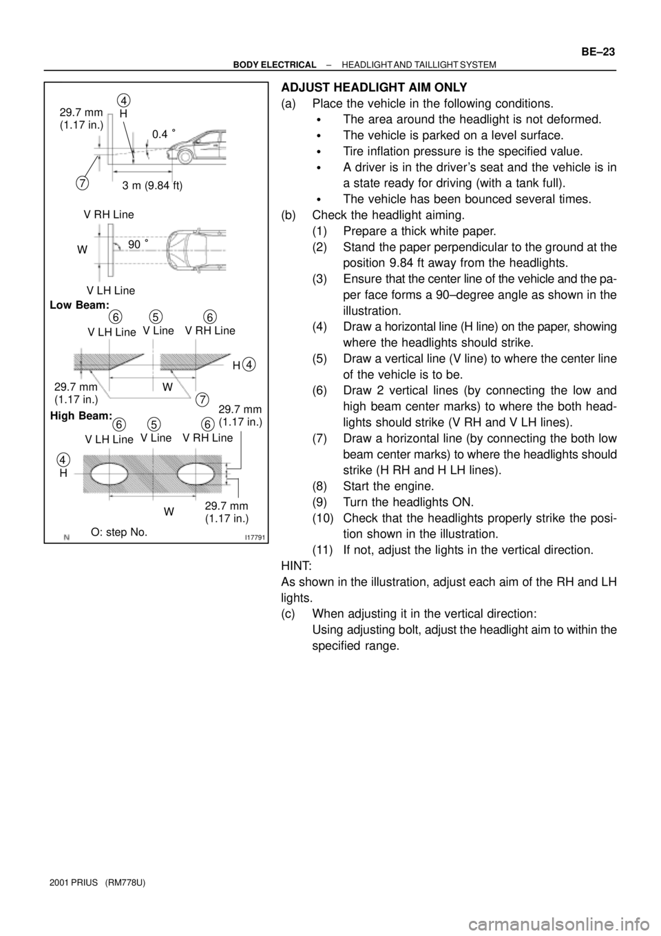
(b) Check the headlight aiming.
(1) Prepare a thick white paper.
(2) Stand the paper perpendicular to the ground at the
position 9.84 ft away from the headlights.
(3) Ensure that the center line of the vehicle and the pa-
per face forms a 90±degree angle as shown in the
illustration.
(4) Draw a horizontal line (H line) on the paper, showing
where the headlights should strike.
(5) Draw a vertical line (V line) to where the center line
of the vehicle is to be.
(6) Draw 2 vertical lines (by connecting the low and
high beam center marks) to where the both head-
lights should strike (V RH and V LH lines).
(7) Draw a horizontal line (by connecting the both low
beam center marks) to where the headlights should
strike (H RH and H LH lines).
(8) Start the engine.
(9) Turn the headlights ON.
(10) Check that the headlights properly strike the posi-
tion shown in the illustration.
(11) If not, adjust the lights in the vertical direction.
HINT:
As shown in the illustration, adjust each aim of the RH and LH
lights.
(c) When adjusting it in the vertical direction:
Using adjusting bolt, adjust the headlight aim to within the
specified range.