Page 437 of 1943

BODY ELECTRICAL ± ACCESSORIES175
4. Construction and Operation
General
This system mainly consists of a multi-information display, navigation ECU, display ECU, gateway ECU,
GPS antenna and audio unit.
The navigation ECU, display ECU, gateway ECU, and the audio unit all maintain communication through
the AVC-LAN.
Navigation ECU
The navigation ECU is provided on the models with the GPS voice navigation. Based on the map data on
the DVD, signals from the GPS satellites, signals from the built-in gyro sensor, and signals from the ve-
hicle's speed sensor, this ECU calculates the vehicle's present position, direction of travel, and driven dis-
tance, and transmits the data to the display ECU. In addition, it outputs navigation voice instructions.
Display ECU
Upon receiving the vehicle information that is transmitted by the gateway ECU, the navigation information
that is transmitted by the navigation ECU, and the operation information from the audio unit, the display
ECU displays these data on the multi-information display.
Gateway ECU
The gateway ECU transmits the vehicle information to the display ECU in order for it to be displayed on
multi-information display. Because vehicle information is transmitted by the ECUs that maintain commu-
nication on the BEAN (Body Electronics Area Network), the gateway ECU converts this information into
signals for AVC-LAN use and sends it to the display ECU.
GPS Antenna
The GPS antenna is provided on the models with the GPS voice navigation.
The GPS antenna receives signals from the GPS satellites that are located on the orbits that circle the earth
at an approximate altitude of 20,000 km. The GPS satellites continuously transmit orbit signals and the sig-
nal transmission time.
Multi-information Display
�The multi-information display has the functions for displaying the map screen, audio screen, information
screen, adjustment screen, interrupt screen, and on-screen.
�This system's self-diagnosis function can be displayed and operated on the multi-information display.
For details, refer to the 2001 Prius Repair Manual (Pub. No. RM778U).
Page 499 of 1943

IN04Q±11
IN±46
± INTRODUCTIONTERMS
46 Author�: Date�:
2001 PRIUS (RM778U)
TERMS
ABBREVIATIONS USED IN THIS MANUAL
AbbreviationsMeaning
ABSAnti±Lock Brake System
ACAlternating Current
ACCAccessory
ACISAcoustic Control Induction System
ACSDAutomatic Cold Start Device
A.D.D.Automatic Disconnecting Differential
A/FAir±Fuel Ratio
AHCActive Height Control Suspension
ALRAutomatic Locking Retractor
ALTAlternator
AMPAmplifier
ANTAntenna
APPROX.Approximately
A/TAutomatic Transmission (Transaxle)
AT FAutomatic Transmission Fluid
AUTOAutomatic
AUXAuxiliary
AV GAverage
AV SAdaptive Variable Suspension
BABrake Assist
BACSBoost Altitude Compensation System
BATBattery
BDCBottom Dead Center
B/LBi±Level
B/SBore±Stroke Ratio
BTDCBefore Top Dead Center
BVSVBimetallic Vacuum Switching Valve
Calif.California
CBCircuit Breaker
CCoCatalytic Converter For Oxidation
CDCompact Disc
CFCornering Force
CGCenter Of Gravity
CHChannel
COMB.Combination
CPECoupe
CPSCombustion Pressure Sensor
CPUCentral Processing Unit
CRSChild Restraint System
CTRCenter
C/VCheck Valve
CVControl Valve
Page 501 of 1943

IN±48
± INTRODUCTIONTERMS
48 Author�: Date�:
2001 PRIUS (RM778U) H/B
Hatchback
H±FUSEHigh Current Fuse
HIHigh
HIDHigh Intensity Discharge (Head Lamp)
HSGHousing
HTHard Top
HVHybrid Vehicle
HWSHeated Windshield System
IACIdle Air Control
ICIntegrated circuit
IDIIndirect Diesel Injection
IFSIndependent Front Suspension
IGIgnition
IIAIntegrated Ignition Assembly
INIntake (Manifold, Valve)
INTIntermittent
I/PInstrument Panel
IRSIndependent Rear Suspension
J/BJunction Block
J/CJunction Connector
KDKick±Down
LANLocal Area Network
LBLiftback
LCDLiquid Crystal Display
LEDLight Emitting Diode
LHLeft±Hand
LHDLeft±Hand Drive
L/H/WLength, Height, Width
LLCLong±Life Coolant
LNGLiquified Natural Gas
LOLow
LPGLiquified Petroleum Gas
LSDLimited Slip Differential
LSP & PVLoad Sensing Proportioning And Bypass Valve
LSPVLoad Sensing Proportioning Valve
MAX.Maximum
MG1Motor Generator No. 1
MG2Motor Generator No. 2
MICMicrophone
MILMalfunction Indicator Lamp
MIN.Minimum
MPMultipurpose
MPXMultiplex Communication System
M/TManual Transmission
MTMount
MTGMounting
Page 613 of 1943

N09214
FI2547
± DIAGNOSTICSENGINE
DI±5
2001 PRIUS (RM778U)
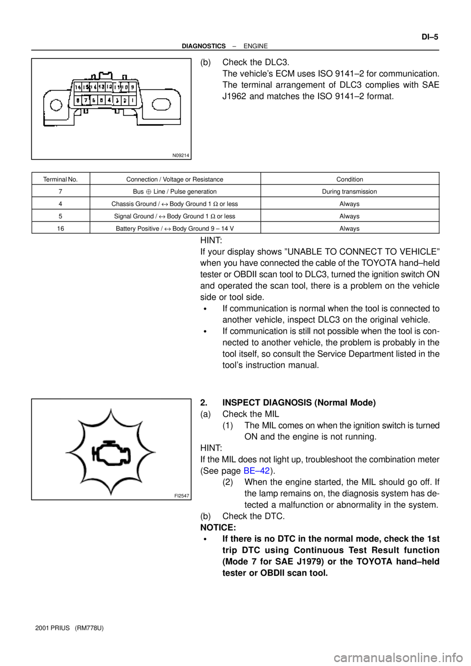
(b) Check the DLC3.
The vehicle's ECM uses ISO 9141±2 for communication.
The terminal arrangement of DLC3 complies with SAE
J1962 and matches the ISO 9141±2 format.
Terminal No.Connection / Voltage or ResistanceCondition
7Bus � Line / Pulse generationDuring transmission
4Chassis Ground / e Body Ground 1 W or lessAlways
5Signal Ground / e Body Ground 1 W or lessAlways
16Battery Positive / e Body Ground 9 ± 14 VAlways
HINT:
If your display shows ºUNABLE TO CONNECT TO VEHICLEº
when you have connected the cable of the TOYOTA hand±held
tester or OBDII scan tool to DLC3, turned the ignition switch ON
and operated the scan tool, there is a problem on the vehicle
side or tool side.
�If communication is normal when the tool is connected to
another vehicle, inspect DLC3 on the original vehicle.
�If communication is still not possible when the tool is con-
nected to another vehicle, the problem is probably in the
tool itself, so consult the Service Department listed in the
tool's instruction manual.
2. INSPECT DIAGNOSIS (Normal Mode)
(a) Check the MIL
(1) The MIL comes on when the ignition switch is turned
ON and the engine is not running.
HINT:
If the MIL does not light up, troubleshoot the combination meter
(See page BE±42).
(2) When the engine started, the MIL should go off. If
the lamp remains on, the diagnosis system has de-
tected a malfunction or abnormality in the system.
(b) Check the DTC.
NOTICE:
�If there is no DTC in the normal mode, check the 1st
trip DTC using Continuous Test Result function
(Mode 7 for SAE J1979) or the TOYOTA hand±held
tester or OBDII scan tool.
Page 618 of 1943

A04438A13924A14466
TC
CG
A14060
DI±10
± DIAGNOSTICSENGINE
2001 PRIUS (RM778U)
5 Check ignition timing.
PREPARATION:
(a) Warm up engine to normal operating temperature.
(b) Shift transmission into P position.
(c) Keep the engine speed at idle.
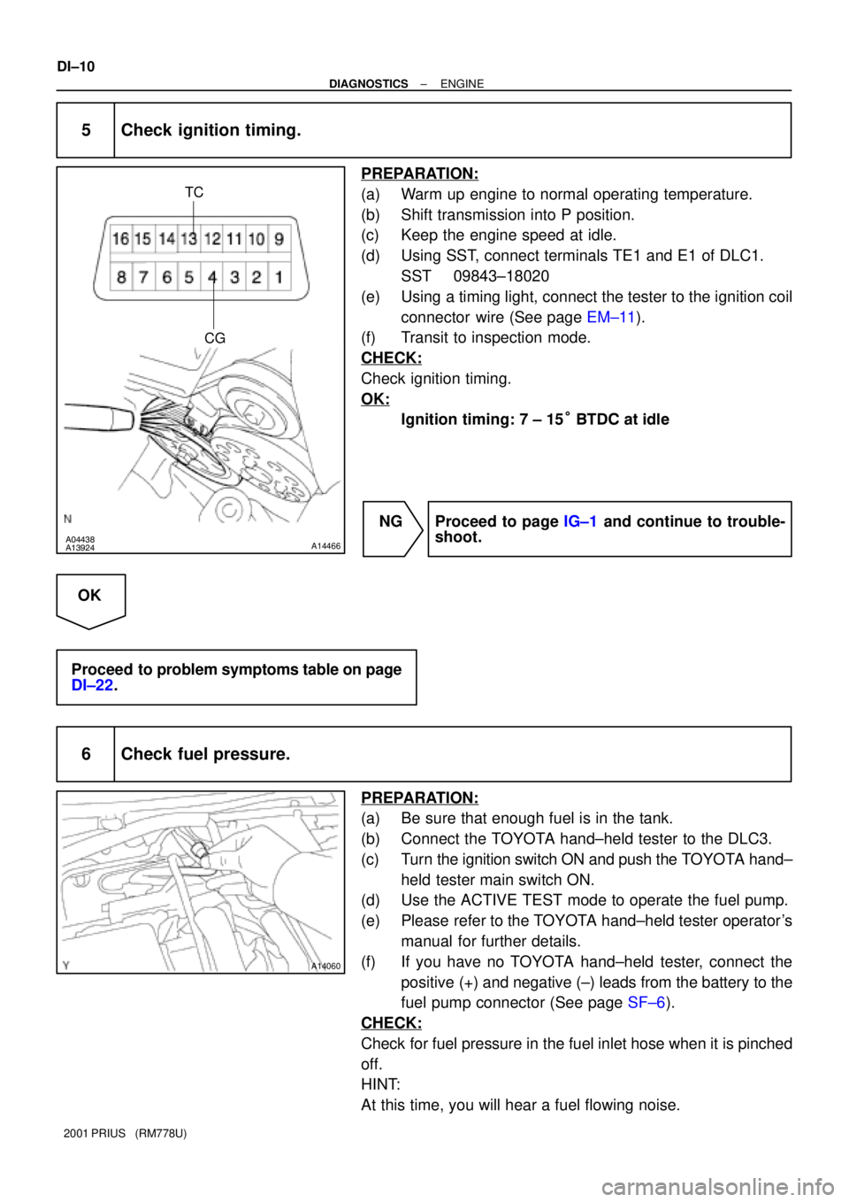
(d) Using SST, connect terminals TE1 and E1 of DLC1.
SST 09843±18020
(e) Using a timing light, connect the tester to the ignition coil
connector wire (See page EM±11).
(f) Transit to inspection mode.
CHECK:
Check ignition timing.
OK:
Ignition timing: 7 ± 15° BTDC at idle
NG Proceed to page IG±1 and continue to trouble-
shoot.
OK
Proceed to problem symptoms table on page
DI±22.
6 Check fuel pressure.
PREPARATION:
(a) Be sure that enough fuel is in the tank.
(b) Connect the TOYOTA hand±held tester to the DLC3.
(c) Turn the ignition switch ON and push the TOYOTA hand±
held tester main switch ON.
(d) Use the ACTIVE TEST mode to operate the fuel pump.
(e) Please refer to the TOYOTA hand±held tester operator's
manual for further details.
(f) If you have no TOYOTA hand±held tester, connect the
positive (+) and negative (±) leads from the battery to the
fuel pump connector (See page SF±6).
CHECK:
Check for fuel pressure in the fuel inlet hose when it is pinched
off.
HINT:
At this time, you will hear a fuel flowing noise.