CHASSIS ± P111 HYBRID TRANSAXLE
182CH25
182CH26Shift Position
Sensor
Shift
Position
SensorMain
Sub
HV
ECU
Serial Data
LinkEngine
ECUCombination
Meter
Voltage
: Defined
: Region
Voltage
Signal
Stroke B
D
N
R
P
PRNDBSwitch
Signal
Service Tip
Because it is extremely difficult to precisely assemble the shift position sensors, do not disassemble the
shift lever. 88
�SHIFT CONTROL
1. Shift Lever
A column-type shift lever with 5 positions has been adopted. The shift lever is operated by moving it in the
vehicle's longitudinal direction to ensure excellent ease of use. The shift lever is integrated with the shift posi-
tion sensor.
2. Shift Control
For shift control, a shift-by-wire system has been
adopted. This system uses electrical signals that
are output by the shift position sensor to determine
the shift position. For operating the parking lock
pawl in the transaxle, however, a shift cable is used
for attaining P position.
The shift position sensor outputs two systems of
signals: the main switch signals, and the sub
switch signals containing high and low voltages.
When these signals match, the HV ECU deter-
mines the respective shift position.
IN0253
WRONG CORRECT
IN0252
WRONG CORRECT IN±6
± INTRODUCTIONREPAIR INSTRUCTIONS
6 Author�: Date�:
2001 PRIUS (RM778U)
(k) Care must be taken when jacking up and supporting the
vehicle. Be sure to lift and support the vehicle at the prop-
er locations (See page IN±8).
�Cancel the parking brake on the pedal place and
shift the transmission in N position.
�When jacking up the front wheels of the vehicle at
first place stoppers behind the rear wheels.
�When jacking up the rear wheels of the vehicle at
first place stoppers before the front wheels.
�When either the front or rear wheels only should be
jacked up, set rigid racks and place stoppers in front
and behind the other wheels on the ground.
�After the vehicle is jacked up, be sure to support it
on rigid racks . It is extremely dangerous to do any
work on a vehicle raised on a jack alone, even for
a small job that can be finished quickly.
(l) Observe the following precautions to avoid damage to the
following parts:
(1) Do not open the cover or case of the ECU unless
absolutely necessary. (If the IC terminals are
touched, the IC may be destroyed by static electric-
ity.)
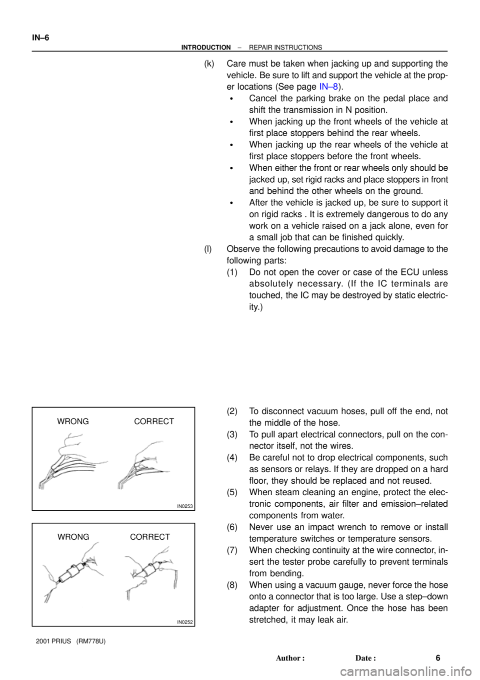
(2) To disconnect vacuum hoses, pull off the end, not
the middle of the hose.
(3) To pull apart electrical connectors, pull on the con-
nector itself, not the wires.
(4) Be careful not to drop electrical components, such
as sensors or relays. If they are dropped on a hard
floor, they should be replaced and not reused.
(5) When steam cleaning an engine, protect the elec-
tronic components, air filter and emission±related
components from water.
(6) Never use an impact wrench to remove or install
temperature switches or temperature sensors.
(7) When checking continuity at the wire connector, in-
sert the tester probe carefully to prevent terminals
from bending.
(8) When using a vacuum gauge, never force the hose
onto a connector that is too large. Use a step±down
adapter for adjustment. Once the hose has been
stretched, it may leak air.