Page 17 of 1943
*The titles given inside the components are the names of the terminals (terminal codes) and are not treated as being
abbreviations.
2001 PRIUS (EWD414U)
ABBREVIATIONS D
ABBREVIATIONS
The following abbreviations are used in this manual.
ABS = Anti±Lock Brake System
A/C = Air Conditioning
COMB. = Combination
DC = Direct Current
ECU = Electronic Control Unit
EMPS = Electric Motor Power Steering
ESA = Electronic Spark Advance
EVAP = Evaporative Emission
HV = Hybrid Vehicle
J/B = Junction Block
LH = Left±Hand
PTC = Positive Temperature Coefficient
R/B = Relay Block
RH = Right±Hand
SFI = Sequential Multiport Fuel Injection
SRS = Supplemental Restraint System
SW = Switch
TEMP. = Temperature
VSV = Vacuum Switching Valve
w/ = With
w/o = Without
Page 72 of 1943

2001 PRIUS (EWD414U)
ENGINE CONTROL
This system utilizes an engine control module and maintains overall control of the engine, transmission and so on. An outline
of the engine control is explained here.
1. INPUT SIGNALS
(1) Engine coolant temp. signal circuit
The engine coolant temp. sensor detects the engine coolant temp. and has a built±in thermistor with a resistance which
varies according to the engine coolant temp. thus the engine coolant temp. is input in the form of a control signal into
TERMINAL THW of the engine control module.
(2) Intake air temp. signal circuit
The intake air temp. sensor is installed in the mass air flow meter and detects the intake air temp., which is input as a
control signal into TERMINAL THA of the engine control module.
(3) Oxygen sensor signal circuit
The oxygen density in the exhaust gases is detected and input as a control signal into TERMINALS OX1A and OX1B of
the engine control module.
(4) RPM signal circuit
Camshaft position and crankshaft position are detected by the camshaft position sensor and crankshaft position sensor.
Camshaft position is input as a control signal to TERMINAL G2 of the engine control module, and engine RPM is input
into TERMINAL NE+.
(5) Throttle signal circuit
The throttle position sensor detects the throttle valve opening angle, which is input as a control signal into TERMINALS
VTA and VTA2 of the engine control module.
(6) Vehicle speed signal circuit
The vehicle speed signal from brake ECU, detects the vehicle speed and inputs a control signal into TERMINAL SPD of
the engine control module via the combination meter.
(7) Battery signal circuit
Voltage is constantly applied to TERMINAL BATT of the engine control module. When the ignition SW is turned on, the
voltage for engine control module start±up power supply is applied to TERMINAL +B of the engine control module via
EFI relay.
(8) Engine knock signal circuit
Engine knocking is detected by knock sensor and the signal is input into TERMINAL KNK1 of the engine control module
as a control signal.
2. CONTROL SYSTEM
*SFI system
The SFI system monitors the engine condition through the signals, which are input from each sensor to the engine
control module. The best fuel injection volume is decided based on this data and the program memorized by the engine
control module, and the control signal is output to TERMINALS #10, #20, #30 and #40 of the engine control module to
operate the injector. (Inject the fuel). The SFI system produces control of fuel injection operation by the engine control
module in response to the driving conditions.
*ESA system
The ESA system monitors the engine condition through the signals, which are input to the engine control module from
each sensor. The best ignition timing is detected according to this data and the memorized data in the engine control
module, and the control signal is output to TERMINALS IGT1, IGT2, IGT3 and IGT4. This signal controls the ignition coil
and igniter to provide the best ignition timing for the driving conditions.
*Fuel pump control system
The engine control module operation outputs to TERMINAL FC and controls the CIR OPN relay. Thus controls the fuel
pump drive speed in response to conditions.
3. DIAGNOSIS SYSTEM
With the diagnosis system, when there is a malfunctioning in the engine control module signal system, the malfunction
system is recorded in the memory. The malfunctioning system can then be found by reading the display (Code) of the
malfunction indicator lamp.
4. FAIL±SAFE SYSTEM
When a malfunction occurs in any system, if there is a possibility of engine trouble being caused by continued control based
on the signals from that system, the fail±safe system either controls the system by using data (Standard values) recorded in
the engine control module memory or else stops the engine.
SYSTEM OUTLINE
Page 186 of 1943
2001 PRIUS (EWD414U)
AIR CONDITIONING
50A
HTR FROM POWER SOURCE SYSTEM (
SEE PAGE 50)
23 415
1K 81J13 1A51F3 32 51
1F 4
A A A A
B A
2 1
3 3
25 13
33
1 2
IE4
1 1K 3
IE1 8
IE113
E 5
L
L±R
W±B W± BL±R
W±BV R B±L LG±RL±O
R
R
B±R
L±O
B±L
LG±R
R
W±B B±W
B±R
VB±R
L±Y L±YW±B
W±B
W±B W±B
12 3B
AAAA
A A 4BB
BLOWER MOTOR
LINEAR CONTROLLER B 7
JUNCTION
CONNECTOR J 7 JUNCTION
CONNECTOR J 6
BLOWER
MOTOR B 6
WAT ER PU MP
MOTOR (
A/C) W 2
JUNCTION
CONNECTOR J 1
A/C DUAL PRESSURE SW A 3JUNCTION
CONNECTORB J 2 A , J 3
2
HTR
RELAYCLR MG
RELAY
W±B
LG±R
RA/C W/P
RELAY 1
GNDSI +B VMM
M
Page 188 of 1943
2001 PRIUS (EWD414U)
AIR CONDITIONING
2F 6
A 11 A4D 14 D13 C23
D 3D22 B18
B 4B5IA2 5
1 2
C 5 C 6
M C 20 C18 C19 C22 C21
1 34 18
211
2 12345
L±O
GR±B
GR GR
GR±B
LG
P±G
BR W±G
W±G BR±W W W
W
W
W
W
W
GR±L
W
COMBINATION METER C11
GATEWAY ECU G 1
AMBIENT TEMP. SENSOR A 6 ENGINE CONTROL MODULEC E 8 B , E 9
MPX± MPD1 HRLY MPX+MPX±
MEO2 ACT E2
S5TS TS SGTPI S5TPI TPI AIF AIR MPX+ MPD2 MPX1 MPX2 TAM
MPX+ MP2+ NE ACT
D , E10 A/C SOLAR
SENSOR A11
AIR INLET CONTROL SERVO MOTOR A14 C , A 9 AA 8, A 7 B
A/C AMPLIFIER BODY ECUB 8 A
A 15A 16
IK1 2
Page 190 of 1943
2001 PRIUS (EWD414U)
AIR CONDITIONING
30A
HTR2 FROM POWER SOURCE SYSTEM (
SEE PAGE 50)
330A
HTR1
3
33 33
33 33
B 6B 1315 23
25 13 3 1
5 2
3 33 3 2G 810A
GAU GE
3
IE118
IA1 1IA15
ID C , A 9 AA 8, A 7 B
A/C AMPLIFIERP
P±BPR±L R±L
P±B
R±L
G
G±W
B±R W±B
W±B W±B
W±B
JUNCTION
CONNECTOR J11 AA
L±R
HTR1
RELAY HTR2
RELAY HTR3
RELAY11
22
P±B
IE116
IE
W±B
JUNCTION
CONNECTOR J 1 A 1
50A
HTR3
2
HTROHTR2B 1 B 3
B 2 B 4PTC HEATERB P 3 , P 4A A 1
A 2
W±B
G±R
L±Y
Page 192 of 1943
2001 PRIUS (EWD414U)
AIR CONDITIONING
: SPLICE POINTS
CodeSee PageWire Harness with Splice PointsCodeSee PageWire Harness with Splice Points
E540Engine Room Main Wire
Page 202 of 1943

2001 PRIUS (EWD414U)
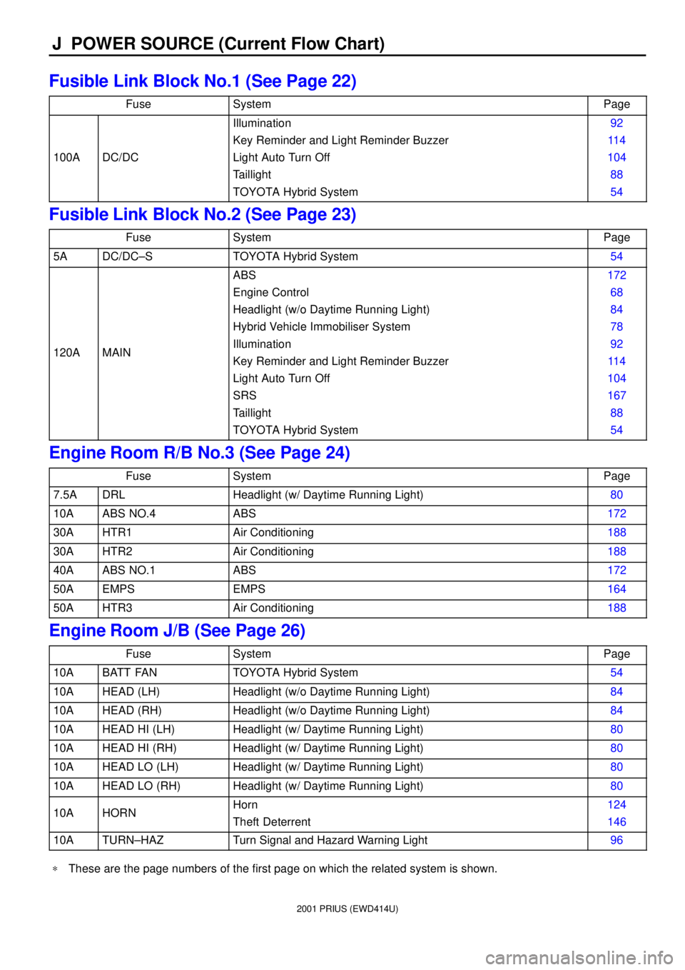
J POWER SOURCE (Current Flow Chart)
Fusible Link Block No.1 (See Page 22)
FuseSystemPage
100ADC/DC
Illumination
Key Reminder and Light Reminder Buzzer
Light Auto Turn Off
Taillight
TOYOTA Hybrid System92
11 4
104
88
54
Fusible Link Block No.2 (See Page 23)
FuseSystemPage
5ADC/DC±STOYOTA Hybrid System54
120AMAIN
ABS
Engine Control
Headlight (w/o Daytime Running Light)
Hybrid Vehicle Immobiliser System
Illumination
Key Reminder and Light Reminder Buzzer
Light Auto Turn Off
SRS
Taillight
TOYOTA Hybrid System172
68
84
78
92
11 4
104
167
88
54
Engine Room R/B No.3 (See Page 24)
FuseSystemPage
7.5ADRLHeadlight (w/ Daytime Running Light)80
10AABS NO.4ABS172
30AHTR1Air Conditioning188
30AHTR2Air Conditioning188
40AABS NO.1ABS172
50AEMPSEMPS164
50AHTR3Air Conditioning188
Engine Room J/B (See Page 26)
FuseSystemPage
10ABATT FANTOYOTA Hybrid System54
10AHEAD (LH)Headlight (w/o Daytime Running Light)84
10AHEAD (RH)Headlight (w/o Daytime Running Light)84
10AHEAD HI (LH)Headlight (w/ Daytime Running Light)80
10AHEAD HI (RH)Headlight (w/ Daytime Running Light)80
10AHEAD LO (LH)Headlight (w/ Daytime Running Light)80
10AHEAD LO (RH)Headlight (w/ Daytime Running Light)80
10AHORNHorn
Theft Deterrent124
146
10ATURN±HAZTurn Signal and Hazard Warning Light96
*These are the page numbers of the first page on which the related system is shown.
Page 203 of 1943

2001 PRIUS (EWD414U)
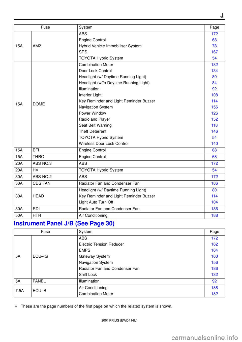
J
FuseSystemPage
15AAM2
ABS
Engine Control
Hybrid Vehicle Immobiliser System
SRS
TOYOTA Hybrid System172
68
78
167
54
15ADOME
Combination Meter
Door Lock Control
Headlight (w/ Daytime Running Light)
Headlight (w//o Daytime Running Light)
Illumination
Interior Light
Key Reminder and Light Reminder Buzzer
Navigation System
Power Window
Radio and Player
Seat Belt Warning
Theft Deterrent
TOYOTA Hybrid System
Wireless Door Lock Control182
134
80
84
92
108
11 4
156
126
152
11 8
146
54
140
15AEFIEngine Control68
15ATHROEngine Control68
20AABS NO.3ABS172
20AHVTOYOTA Hybrid System54
30AABS NO.2ABS172
30ACDS FANRadiator Fan and Condenser Fan186
30AHEAD
Headlight (w/ Daytime Running Light)
Key Reminder and Light Reminder Buzzer
Light Auto Turn Off80
11 4
104
30ARDIRadiator Fan and Condenser Fan186
50AHTRAir Conditioning188
Instrument Panel J/B (See Page 30)
FuseSystemPage
5AECU±IG
ABS
Electric Tension Reducer
EMPS
Gateway System
Navigation System
Radiator Fan and Condenser Fan
Shift Lock172
162
164
160
156
186
132
5APANELIllumination92
7.5AECU±BAir Conditioning
Combination Meter188
182
*These are the page numbers of the first page on which the related system is shown.