2001 TOYOTA PRIUS cruise control
[x] Cancel search: cruise controlPage 8 of 1943
2001 PRIUS (EWD414U)
B HOW TO USE THIS MANUAL
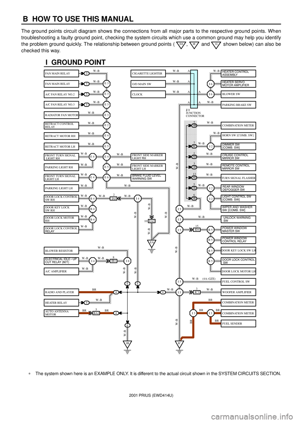
The ground points circuit diagram shows the connections from all major parts to the respective ground points. When
troubleshooting a faulty ground point, checking the system circuits which use a common ground may help you identify
the problem ground quickly. The relationship between ground points (
EA, IB and IC shown below) can also be
checked this way.
���� ���� ���� ���� ���� ���� ���� ���� ���� ���� ���� ���� ���� ���� ���� ���� ���� ���� ����
I GROUND POINT
FAN MAIN RELAY
FAN MAIN RELAY
A/C FAN RELAY NO.2
A/C FAN RELAY NO.3
RADIATOR FAN MOTOR
RETRACT CONTROL
RELAY
RETRACT MOTOR RH
RETRACT MOTOR LH
FRONT TURN SIGNAL
LIGHT RH
PARKING LIGHT RH
FRONT TURN SIGNAL
LIGHT LH
PARKING LIGHT LH
DOOR LOCK CONTROL
SW RH
DOOR KEY LOCK
SW RH
DOOR LOCK MOTOR
RH
BLOWER RESISTOR
A/C AMPLIFIER
RADIO AND PLAYER
HEATER RELAY
AUTO ANTENNA
MOTOR
BLOWER SW
PARKING BRAKE SW
COMBINATION METER
HORN SW [COMB. SW]
TURN SIGNAL FLASHER
DOOR KEY LOCK SW LH
DOOR LOCK MOTOR LH
FUEL CONTROL SW
WOOFER AMPLIFIER
COMBINATION METER
COMBINATION METER
FUEL SENDER
CIGARETTE LIGHTER
O/D MAIN SW
CLOCK
5
5
5
5
4
4
4
4
4BA15
IB18
EA2 10
3E5
3E
6 3G
13 3F
3 3D
1 3B
7
ID115
IC33
IA12
E 3
A
A AW±B
W±BW±B W±B
W±B W±B
W±B
W±B
W±B
W±B
W±B
W±B
W±B
W±B
W±B W±BW±B W±B W±B W±B
W±B W±B
W±BW±B
W±B
W±B
W±B W±B
W±B
BR
W±B
BR BRW±BW±B
W±B
W±B
W±B
W±B
W±B
W±B
W±B
W±B
W±B W±B
W±B
W±B
W±B
W±B
BR W±B
BR BR
BR W±B W±BW±B
W±BW±BBR W±B (4A±GZE)
W±B A A A
I 6
I 6
I 2
I 2
I 2
B 5I 5
I 5
I 5
B 5
B 5
B 5
I 5
I 5
I 3I 3
E 3
E 3
E 3
E 2
E 4
E 5
E 4
E 5
E 6E 4
E 4
B 4
EAI 4
B 4
B 4
I 4I 8
IBIC
3C7
4
JUNCTION
CONNECTOR J 1
4
DOOR LOCK CONTROL
RELAY
ELECTRICAL IDLE-UP
CUT RELAY (M/T)FRONT SIDE MARKER
LIGHT RH
FRONT SIDE MARKER
LIGHT LH
BRAKE FLUID LEVEL
WARNING SW
UNLOCK WARNING
SW WIPER AND WASHER
SW [COMB. SW] LIGHT CONTROL SW
[COMB. SW] HEATER CONTROL
ASSEMBLY
HEATER SERVO
MOTOR AMPLIFIER
DIMMER SW
[COMB. SW]
CRUISE CONTROL
MIRROR SW
REAR WINDOW
DEFOGGER SW
POWER WINDOW
MASTER SW
POWER WINDOW
CONTROL RELAY
DOOR LOCK CONTROL
SW
REMOTE CONTROL
MIRROR SW
*The system shown here is an EXAMPLE ONLY. It is different to the actual circuit shown in the SYSTEM CIRCUITS SECTION.
Page 9 of 1943
2001 PRIUS (EWD414U)
B
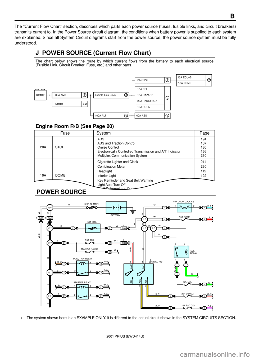
The ºCurrent Flow Chartº section, describes which parts each power source (fuses, fusible links, and circuit breakers)
transmits current to. In the Power Source circuit diagram, the conditions when battery power is supplied to each system
are explained. Since all System Circuit diagrams start from the power source, the power source system must be fully
understood.
Theft Deterrent and Door Lock Control
J POWER SOURCE (Current Flow Chart)
11
1
EA1 1EA2 3
7
EB16
E 6
E 7I 2I 2
I 2
E 7
E 7
E 7
2
1
1
2
2
2
2
2
B
B
W W
B B B B BW±B
B
B
B B±O
B±W
W±B
B±W STARTER RELAY INJECTION RELAY15A HAZ±RADIO7.5A AM250A MAIN 1.25B FL MAIN
BATTERY
WWW
W W W
R W±L
W
W
G±W
G
15A TAIL
20A DEFOG
15A RAD CIGTA I L
RELAY 7.5A DOME 40A DOOR LOCK CB
2 1
1 2
4 8
2 3
3 4
G
W±R
P±L B±Y
B±Y
W±R
AM2 IG2
ACC
IG1AM1W W
W±R
W W
W±B
21
1
1
1
1
2
2
2
2
3
4
3
4 1
2
1
22
1
11
1
IGNITION SW I 8
Battery
30A AM2
2
Starter S 220A RADIO NO.1
10A HORN
15A EFI
7.5A DOMEShort Pin
10A HAZARD
The chart below shows the route by which current flows from the battery to each electrical source
(Fusible Link, Circuit Breaker, Fuse, etc.) and other parts.
Engine Room R/B (See Page 20)
ABS
ABS and Traction Control
Cruise Control
Electronically Controlled Transmission and A/T Indicator
Multiplex Communication System
Cigarette Lighter and Clock
Key Reminder and Seat Belt Warning STOP
Fuse Page
194
214
11 2
System
DOME 20A
10ACombination Meter
Headlight
Interior Light
2
2
6 100A ALT
EB1
POWER SOURCE
Light Auto Turn Off187
180
166
210
230
122
10A ECU±B
5 60A ABS
2
6 Fusible Link Block2
*The system shown here is an EXAMPLE ONLY. It is different to the actual circuit shown in the SYSTEM CIRCUITS SECTION.
Page 52 of 1943
2001 PRIUS (EWD414U)
TOYOTA HYBRID SYSTEM
C 1
1D1B 215A
AM2 1J 9ST2IG2 AM2 6
BATTERY7
IGNITION SW I15
FUSIBLE
LINK
BLOCK
NO. 1D F1 2 , F13C
B±G B W±R W±R
2C 2
2G 1
120A MAIN
1
FUSIBLE
LINK BLOCK
NO. 2 F18A CACE 7
B B
ID1 63 4D 2D16 ST1± IGSW CCS
B±W
B±Y
L LB±W
B±W
E 6ST2
R±W
STOP LIGHT SW S 3
B±W 8
IGA AAAB A B A B AD 31 D24
5
A 4
CRUISE CONTROL SW
[COMB. SW] C14
W±B W±B
W±B
W±BW±B
W±B
D 1STP GND1 GND2
G±W
JUNCTION
CONNECTOR J17
FROM STOP LIGHT
SW
W±B JUNCTION
CONNECTORB J18 , J19A
JUNCTION
CONNECTORB J24 A , J25
H14 , D H13 , E H12 , B CH11, H10 A
HYBRID VEHICLE CONTROL ECU
B±W
CCS
CRUISE
RES/ACC
SET/COAST
CANCEL 11 2G52B
1J 3
32 51
1A 21K3
IK1 14
M
1 2
E 5
B±W B±W B±W
W±B W±B W±B
W± B
WATER PUMP MOTOR
(
INVERTER) W 3
IG2
RELAYB±W
B±W
R±W
W±B ECC
Page 58 of 1943
2001 PRIUS (EWD414U)
TOYOTA HYBRID SYSTEM
BJA 22A 17 A16 IB1 10 IB16 D 26 D25
R±W
B±L W± B W± B
R±W
B±LR±W
B± L
BATTERY ECUB B1 7 , B1 8A HYBRID VEHICLE CONTROL ECUA H10 , H11
CB, H12
E , H13
D , H14
GB 1B
O(
*2)
O(
*2)
IHO(
*2)
GR±B
GR
BR
10A
GAUGE FROM POWER SOURCE SYSTEM (
SEE PAGE 50)
2A 515A
DOME
1J 7
L±Y
2G 2
2A 4L
L
A 21 A 22
CHARGE
OU TPUT
CONTROL
CRUISE
A 14 B2
L
COMBINATION METERB C10 , C11A
LV±W
2B 7
2A 6
A 13A G
B GIE1 19B 8SPDI
JUNCTION
CONNECTORB J27 , J28A
V±W V±W
W±R
2A 1IH1I 9 W±GW±G
B 3
62B 72AO(
*2)
W±R GR GR±B L
W± B
W±G
Page 62 of 1943

2001 PRIUS (EWD414U)
TOYOTA HYBRID SYSTEM
FEATURES OF TOYOTA HYBRID SYSTEM
This system controls the following modes in order to achieve the most efficient operations to match the driving conditions.
(1) Supply of electrical power from the HV battery to motor generator no.2 provides force to drive the wheels.
(2) While the tires are driven by the engine via the planetary gears, motor generator no.1 is driven via the planetary gears to
supply electricity to motor generator no.2 to drive the wheels.
(3) When the vehicle is decelerating, kinetic energy from the wheels is recovered and converted into electrical energy and
used to recharge the HV battery by means of motor generator no.2.
The hybrid vehicle control ECU switches between these modes (1, 2, 1+2, or 3) according to the driving conditions.
However, when the state of charge of the HV battery is low, the HV battery is charged by the engine by turning motor
generator no.1.
CRUISE CONTROL OPERATION
Cruise control is the speed control device, which sets the desired speed by just operating the switch on the control panel
without pressing the accelerator pedal. This device is used when you would like to drive the vehicle at the fixed speed.
1. SET CONTROL
If you operate the SET/COAST switch when driving (The available range of set speed: between about 40 and 200 km/h) with
the main switch is ON (When power indicator comes on), the device memorizes vehicle's speed when switch is off and
controls the fixed speed.
2. SET SPEED CONTROL
This device compares the vehicle's running speed and the memorized speed, and controls the driving power of the motor
and the engine by calculating the cruise control requirements so that both speed become equivalent.
3. COAST CONTROL
If the SET/COAST switch is continued to be ON during the running with the cruise control, the device recognizes the cruise
control requirement is at 0 and decelerates the vehicle's speed. Then the device memorizes the speed when the switch is off
in order to control the fixed speed.
In each time you operate SET/COAST switch momentarily (For about 0.5 second), the memorized speed is decreased in
about 1.5 km/h. However, in case of the tap±down operation with more than 5±km/h gap between the memorized speed and
vehicle's running speed, the device memorizes the vehicle's speed when the switch is off and controls the fixed speed.
4. ACCEL CONTROL
If the RESUME/ACCEL switch is continued to be ON during the running with the cruise control, the device recognizes the
cruise control is on the acceleration side and accelerates the vehicle's speed. Then the running speed when the switch is off
is memorized to control the fixed speed.
In each time you operate RESUME/ACCEL switch momentarily (For about 0.5 second), the memorized speed is increased
in about 1.5 km/h. However, if there is more than 5±km/h gap between the memorized speed and vehicle's running speed,
this operation does not change the memorized speed. (Tap±up operation is not available.)
5. RESUME CONTROL
If the running speed is faster than the low speed limit after the cruise control is canceled manually, the fixed speed is
controlled by the OFF±ON operation of RESUME/ACCEL switch, so that the vehicle's speed returns to the memorized
speed at the time the cruise control is released.
SYSTEM OUTLINE
Page 63 of 1943
2001 PRIUS (EWD414U)
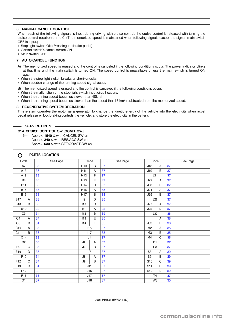
6. MANUAL CANCEL CONTROL
When each of the following signals is input during driving with cruise control, the cruise control is released with turning the
cruise control requirement to 0. (The memorized speed is maintained when following signals except the signal, main switch
OFF is input.)
*Stop light switch ON (Pressing the brake pedal)
*Control switch's cancel switch ON
*Main switch OFF
7. AUTO CANCEL FUNCTION
A) The memorized speed is erased and the control is canceled if the following conditions occur. The power indicator blinks
at that time until the main switch is turned ON. The speed control is unavailable unless the main switch is turned ON
again.
*When the stop light switch breaks or short±circuits.
*When sudden change of the running speed signal occur.
B) The memorized speed is erased and the control is canceled if the following conditions occur.
*When the malfunction of the stop light switch input circuit occurs.
*When the running speed becomes slower than 40km/h.
*When the running speed becomes slower than the speed that 16 km/h subtracted from the memorized speed.
8. REGENERATIVE SYSTEM OPERATION
This system operates the motor as a generator to change the kinetic energy of the vehicle into the electricity when accel
pedal release or foot braking controls the vehicle, and store the electricity in the battery.
C14 CRUISE CONTROL SW [COMB. SW]
5±4 : Approx. 1540 W with CANCEL SW on
Approx. 240 W with RES/ACC SW on
Approx. 630 W with SET/COAST SW on
: PARTS LOCATION
CodeSee PageCodeSee PageCodeSee Page
A736H10C37J18A37
A1336H11A37J19B37
A1836H12B37J2137
B836H13E37J22A37
B1136H14D37J23B37
B1538H16A38J24A37
B1638H17B38J25B37
B17A38I9D35J2637
B18B38I10C35J27A37
B1938I11A35J28B37
C334I12B35J3238
C4A34I13E35A38
C5B34I14F35J33B38
C10A36I1537M2A35
C11B36I1738M3B35
C1436J137M4C35
D236J2A37P137
E9C36J3B37S337
E10D36J737S8A39
F1034J8A37S9B39
F12C34J9B37S10C39
F13D34J1137S11D39
F1738J1637S12E39
F1838J1737T437
G137J1837W335
SERVICE HINTS
Page 182 of 1943
2001 PRIUS (EWD414U)
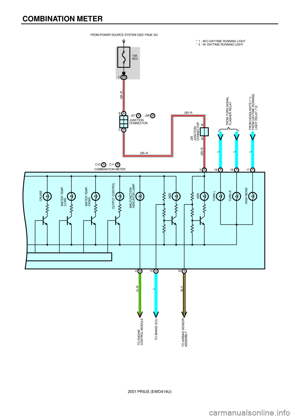
COMBINATION METER
MALFUNCTION
INDICATOR LAMP
ABS
SRS
TURN L
TURN R
HIGH BEAM OUTPUT CONTROLWAT ER TEMP.
(
HIGH) WAT ER TEMP.
(
LOW) CRUISE
A 17 A 18 A 19 B 5
A 16 A 10 B 4
L L L GR± R B±YL G±R
COMBINATION METERB C10 , C11A
FROM HEADLIGHTS (
*1)
FROM DAYTIME RUNNING
LIGHT RELAY (
*2) FROM TURN SI GNAL
FLASHER RELAY TO ENGINE
CONTROL MODULE
TO BRAKE ECU
TO AIRBAG SENSOR
ASSEMBLY
10A
ACC FROM POWER SOURCE SYSTEM (
SEE PAGE 50)
2D 2
GR± R
A B
B C
B B
JUNCTION
CONNECTOR J26
JUNCTION
CONNECTORB J27 , J28AGR ±R
GR± R* 1 : W/O DAYTIME RUNNING LIGHT
* 2 : W/ DAYTIME RUNNING LIGHT
Page 222 of 1943

SYSTEM INDEX
M OVERALL ELECTRICAL WIRING DIAGRAM
2001 PRIUS (EWD414U)
SYSTEMS LOCATION SYSTEMS LOCATION
ABS 19±3. . . . . . . . . . . . . . . . . . . . . . . . . . . . . . . . . . . . . . . . . . . . . . . . . . . . .
Air Conditioning 24±2. . . . . . . . . . . . . . . . . . . . . . . . . . . . . . . . . . . . . . . . . . .
Back±Up Light 6±2. . . . . . . . . . . . . . . . . . . . . . . . . . . . . . . . . . . . . . . . . . . . . .
Cigarette Lighter 11±4. . . . . . . . . . . . . . . . . . . . . . . . . . . . . . . . . . . . . . . . . . . .
Combination Meter 23±2. . . . . . . . . . . . . . . . . . . . . . . . . . . . . . . . . . . . . . . .
Door Lock Control 15±2. . . . . . . . . . . . . . . . . . . . . . . . . . . . . . . . . . . . . . . . .
Electric Tension Reducer 13±4. . . . . . . . . . . . . . . . . . . . . . . . . . . . . . . . . . .
EMPS 20±3. . . . . . . . . . . . . . . . . . . . . . . . . . . . . . . . . . . . . . . . . . . . . . . . . . . .
Engine Control 2±3. . . . . . . . . . . . . . . . . . . . . . . . . . . . . . . . . . . . . . . . . . . . . .
Gateway System 14±8. . . . . . . . . . . . . . . . . . . . . . . . . . . . . . . . . . . . . . . . . .
Headlight (w/ Daytime Running Light) 4±2. . . . . . . . . . . . . . . . . . . . . . . . . .
Headlight (w/o Daytime Running Light) 3±2. . . . . . . . . . . . . . . . . . . . . . . . .
Horn 12±2. . . . . . . . . . . . . . . . . . . . . . . . . . . . . . . . . . . . . . . . . . . . . . . . . . . . .
Hybrid Vehicle Immobiliser System 2±16. . . . . . . . . . . . . . . . . . . . . . . . . . .
Illumination 8±2. . . . . . . . . . . . . . . . . . . . . . . . . . . . . . . . . . . . . . . . . . . . . . . . .
Interior Light 10±3. . . . . . . . . . . . . . . . . . . . . . . . . . . . . . . . . . . . . . . . . . . . . .
Key Reminder and Light Reminder Buzzer 9±2. . . . . . . . . . . . . . . . . . . . . .
Light Auto Turn Off 9±3. . . . . . . . . . . . . . . . . . . . . . . . . . . . . . . . . . . . . . . . . . Navigation System 14±5. . . . . . . . . . . . . . . . . . . . . . . . . . . . . . . . . . . . . . . . .
Power Source 1~24±1. . . . . . . . . . . . . . . . . . . . . . . . . . . . . . . . . . . . . . . . . . .
Power Window 18±2. . . . . . . . . . . . . . . . . . . . . . . . . . . . . . . . . . . . . . . . . . . .
Radiator Fan and Condenser Fan 22±3. . . . . . . . . . . . . . . . . . . . . . . . . . . .
Radio and Player 14±2. . . . . . . . . . . . . . . . . . . . . . . . . . . . . . . . . . . . . . . . . .
Rear Window Defogger 22±2. . . . . . . . . . . . . . . . . . . . . . . . . . . . . . . . . . . . .
Remote Control Mirror 11±2. . . . . . . . . . . . . . . . . . . . . . . . . . . . . . . . . . . . . . .
Seat Belt Warning 9±4. . . . . . . . . . . . . . . . . . . . . . . . . . . . . . . . . . . . . . . . . . .
Shift Lock 13±3. . . . . . . . . . . . . . . . . . . . . . . . . . . . . . . . . . . . . . . . . . . . . . . .
SRS 21±2. . . . . . . . . . . . . . . . . . . . . . . . . . . . . . . . . . . . . . . . . . . . . . . . . . . . .
Stop Light 3±4. . . . . . . . . . . . . . . . . . . . . . . . . . . . . . . . . . . . . . . . . . . . . . . . . .
Taillight 7±2. . . . . . . . . . . . . . . . . . . . . . . . . . . . . . . . . . . . . . . . . . . . . . . . . . . . .
Theft Deterrent 17±2. . . . . . . . . . . . . . . . . . . . . . . . . . . . . . . . . . . . . . . . . . . .
TOYOTA Hybrid System 1±2. . . . . . . . . . . . . . . . . . . . . . . . . . . . . . . . . . . . . .
* Charging
* Cruise Control
* Regenerative Brake
Turn Signal and Hazard Warning Light 5±2. . . . . . . . . . . . . . . . . . . . . . . . . .
Wiper and Washer 12±3. . . . . . . . . . . . . . . . . . . . . . . . . . . . . . . . . . . . . . . . .
Wireless Door Lock Control 16±2. . . . . . . . . . . . . . . . . . . . . . . . . . . . . . . . .