Page 810 of 1943
A14147
H14Hybrid Vehicle
Control ECU
H14
BatteryMAIN
B±G1 1
F1811 1
111
F13 2
3
2
2 Engine Room J/BSTP
ST1± G±W
J15 E
2 J14D J/C
G±W S3
Stop Light
SW
R±B
R±B4B±Y B±W B±W B
B
J24 J25 ID1J/C
B±W
I15
Ignition SW
W±RW±R
67
9
IG2AM2
Instrument Panel J/B
STOP 2C
2K2H 2G9
1J 1BAM2
B
W
F12 F11
DC/DC
Fusible Link Block No. 1 Fusible Link
Block No. 16
± DIAGNOSTICSHYBRID VEHICLE CONTROL SYSTEM
DI±215
2001 PRIUS (RM778U)
DTC P1520 Stop Light Switch (Cruise Control System)
Malfunction
CIRCUIT DESCRIPTION
The HV ECU detects the malfunction of the cruise control system and inhibits the operation of the cruise
control.
It detects faulty output of the STP and ST1± signals sent from the stop light switch or an error signal from
the brake ECU.
DTC P1520 ± Information code 115
INF. code.Detecting ConditionTrouble Area
11 5Open or short in stop light switch circuit
�Stop light switch
�Wire harness
�Brake ECU
WIRING DIAGRAM
DI82R±02
Page 812 of 1943

DTC P1566 Cruise Control System Malfunction
CIRCUIT DESCRIPTION
The HV ECU and the brake ECU monitor the same STP signal. If a")
± DIAGNOSTICSHYBRID VEHICLE CONTROL SYSTEM
DI±217
2001 PRIUS (RM778U)
DTC P1566 Cruise Control System Malfunction
CIRCUIT DESCRIPTION
The HV ECU and the brake ECU monitor the same STP signal. If any difference is identified between both
received signals, the HV ECU outputs an error.
DTC P1566 ± Information code 116
INF. code.Detecting ConditionTrouble Area
11 6When STP signal of HV ECU is inconsistent with that of brake
ECU, with cruise control indicator ON.�Brake ECU
�Wire harness
�Stop light switch
WIRING DIAGRAM
Refer to DI±215.
INSPECTION PROCEDURE
1 Is DTC of brake ECU being output (See page DI±351)?
YES Check DTC of brake ECU (See page DI±351).
NO
2 Check for +B short in wire harness between stop light switch and terminals STP,
ST1±of HV ECU (See page IN±41).
HINT:
Under the normal condition, the voltage of the HV ECU STP terminal is 0V when the brake pedal is released
with the ignition OFF. If there is any output of voltage at this time, the stop light switch circuit has +B short.
NG Repair or replace wire harness.
OK
DI82S±02
Page 901 of 1943
A14138
2A C10
Combination
MeterHybrid Vehicle
Control ECU
L
H12 19
SPDI 68
IE1
13Instrument
Panel J/B
7
2BV±WJ/C
G
J27G
J28V±W V±W DI±310
± DIAGNOSTICSHYBRID VEHICLE CONTROL SYSTEM
2001 PRIUS (RM778U)
DTC P3145 Vehicle Speed Sensor Circuit Malfunction
CIRCUIT DESCRIPTION
DTC P3145 ± Information code 352
INF. code.Detecting ConditionTrouble Area
352No input of vehicle speed signal during cruise control driving�Wire harness
WIRING DIAGRAM
DI83C±02
Page 1207 of 1943

PRE±CHECK
1. ECU TERMINAL VALUES MEASUREMENT BY USING
BREAK±OUT")
DI7NG±01
N09348
Hand±held tester
Break±out±box
F12396DLC3
N17520
± DIAGNOSTICSCRUISE CONTROL SYSTEM
DI±647
2001 PRIUS (RM778U)
PRE±CHECK
1. ECU TERMINAL VALUES MEASUREMENT BY USING
BREAK±OUT±BOX AND HAND±HELD TESTER
(a) Hook up the break±out±box and hand±held tester to the
vehicle.
(b) Read the ECU input/output values by following the
prompts on the tester screen.
(c) Please refer to the hand±held tester has a ºSnapshotº
function. This records the measured data and is effective
in the diagnosis of intermittent problems.
2. USING HAND±HELD TESTER
(a) Hook up the hand±held tester to the DLC3.
(b) Monitor the ECU data by following the prompts on the tes-
ter screen.
HINT:
Hand±held tester has a ºSnapshotº function which records the
monitored data.
Please refer to the hand±held tester operator's manual for fur-
ther details.
3. DTC CLEARANCE
DTC can be deleted using a hand±held tester. If there is no
hand±held tester or it cannot be used, disconnect the auxiliary
battery for 1 min. or more and connect it again.
4. PROBLEM SYMPTOM CONFIRMATION
(ROAD TEST)
(a) Inspect the SET switch.
(1) Push the main switch ON.
(2) Drive at a desired speed (40 km/h (25 mph) or high-
er).
(3) Press the control switch to the SET/COAST.
(4) After releasing the switch, check that the vehicle
cruises at the desired speed.
Page 1208 of 1943

(b) Inspect the ACCEL switch.
(1) Push the main switch ON.
(2) Drive at a desired speed (40 km/h (25 mph) or high")
N17520
N17520
N17520
DI±648
± DIAGNOSTICSCRUISE CONTROL SYSTEM
2001 PRIUS (RM778U)
(b) Inspect the ACCEL switch.
(1) Push the main switch ON.
(2) Drive at a desired speed (40 km/h (25 mph) or high-
er).
(3) Check that the vehicle speed increases while the
control switch is turned to RES/ACC, and that the
vehicle cruises at the set speed when the switch is
released.
(4) Momentarily press the control switch upward in the
RES/ACC and then immediately release it. Check
that the vehicle speed increases by about 1.5 km/h
(Tap±up function).
(c) Inspect the COAST switch.
(1) Push the main switch ON.
(2) Drive at a desired speed (40 km/h (25 mph) or high-
er).
(3) Check that the vehicle speed decreases while the
control switch is turned to SET/COAST, and the ve-
hicle cruises at the set speed when the switch is re-
leased.
(4) Momentarily press the control switch is turned to
SET/COAST, and then immediately release it.
Check that the vehicle speed decreases by about
1.5 km/h (Tap±down function).
(d) Inspect the CANCEL switch.
(1) Push the main switch ON.
(2) Drive at a desired speed (40 km/h (25 mph) or high-
er).
(3) When operating one of the followings, check that
the cruise control system is cancelled and that the
normal driving mode is reset.
�Depress the brake pedal
�Shift to except D range (A/T)
�Push the main switch OFF
Page 1209 of 1943
N17520
N17520
± DIAGNOSTICSCRUISE CONTROL SYSTEM
DI±649
2001 PRIUS (RM778U)
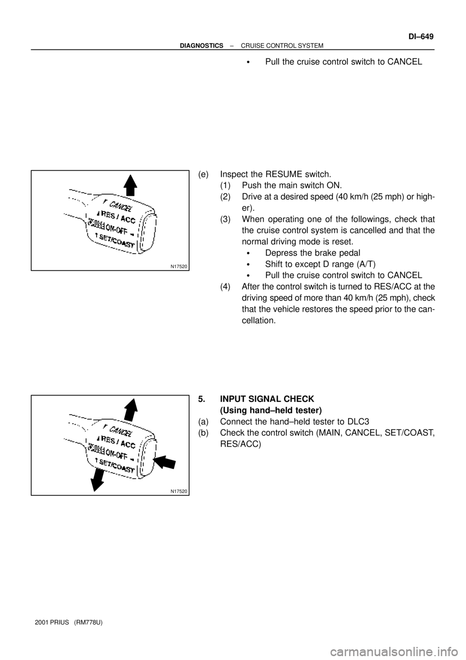
�Pull the cruise control switch to CANCEL
(e) Inspect the RESUME switch.
(1) Push the main switch ON.
(2) Drive at a desired speed (40 km/h (25 mph) or high-
er).
(3) When operating one of the followings, check that
the cruise control system is cancelled and that the
normal driving mode is reset.
�Depress the brake pedal
�Shift to except D range (A/T)
�Pull the cruise control switch to CANCEL
(4) After the control switch is turned to RES/ACC at the
driving speed of more than 40 km/h (25 mph), check
that the vehicle restores the speed prior to the can-
cellation.
5. INPUT SIGNAL CHECK
(Using hand±held tester)
(a) Connect the hand±held tester to DLC3
(b) Check the control switch (MAIN, CANCEL, SET/COAST,
RES/ACC)
Page 1210 of 1943

CIRCUIT INSPECTION
DTC P1520 Stop light switch circuit
CIRCUIT DESCRIPTION
When the brake pedal is depressed, the stop light switch se")
DI±654
± DIAGNOSTICSCRUISE CONTROL SYSTEM
2001 PRIUS (RM778U)
CIRCUIT INSPECTION
DTC P1520 Stop light switch circuit
CIRCUIT DESCRIPTION
When the brake pedal is depressed, the stop light switch sends a signal to the hybrid vehicle control ECU.
When the hybrid vehicle control ECU receives this signal, it cancels the cruise control.
A fail±safe function is provided so that the cancel functions normally, even if there is a malfunction in the stop
light signal circuit.
The cancel condition is that battery voltage is supplied to terminal STP.
When the brake is on, battery voltage is normally applied through the STOP fuse and stop light switch to
terminal STP of the hybrid vehicle control ECU, and the hybrid vehicle control ECU turns the cruise control
OFF.
If the harness connected to terminal STP has an open circuit, terminal STP will have battery voltage and
the cruise control will be turned OFF.
DTC No.Detection ItemTrouble Area
P1520Stop light switch circuit.
�Stop light switch
�Harness or connector between hybrid vehicle control ECU
and stop light switch circuit
�Hybrid vehicle control ECU
DI7NI±01
Page 1211 of 1943
I15477
Instrument Panel J/B
FL Block No. 2S3
Stop Light SW I15
Ignition SW
Engine Room J/BHybrid Vehicle
Control ECU
J25 ID1B±Y
ST1± IG2 AM2
1G±W
2
R±B2
H14
STP 1
H14 B±W
34
6 B±W
J24
B C B±W W±R
7
6
2
2C
15A AM21
2GW±R
9
1J 2
1B B
1
F12B±G
120A MAIN
Battery1
F13
1
F18J15
D J14
E G±W
Instrument Panel J/B
9
2K15A STOP
W
100A DC/DC
F11 1
2H
FL Block No. 1
1
F131
B±GS3
Stop Light SW J/C
J/C
FL Block No. 1
± DIAGNOSTICSCRUISE CONTROL SYSTEM
DI±655
2001 PRIUS (RM778U)
WIRING DIAGRAM