Page 18 of 1943

E GLOSSARY OF TERMS AND SYMBOLS
BATTERY
Stores chemical energy and
converts it into electrical energy.
Provides DC current for the autos
various electrical circuits.GROUND
The p")
2001 PRIUS (EWD414U)
E GLOSSARY OF TERMS AND SYMBOLS
BATTERY
Stores chemical energy and
converts it into electrical energy.
Provides DC current for the auto's
various electrical circuits.GROUND
The point at which wiring attaches to
the Body, thereby providing a return
path for an electrical circuit; without a
ground, current cannot flow.
CAPACITOR (Condenser)
A small holding unit for temporary
storage of electrical voltage.HEADLIGHTS
Current flow causes a headlight
filament to heat up and emit light. A
headlight may have either a single
(1) filament or a double (2) filament
1. SINGLE
FILAMENT
CIGARETTE LIGHTER
An electric resistance heating
element.2. DOUBLE
FILAMENT
CIRCUIT BREAKER
Basically a reusable fuse, a circuit
breaker will heat and open if too
much current flows through it.
Some units automatically reset when
cool, others must be manually reset.HORN
An electric device which sounds a
loud audible signal.
DIODE
A semiconductor which allows
current flow in only one direction.IGNITION COIL
Converts low±voltage DC current
into high±voltage ignition current for
firing the spark plugs.
DIODE, ZENERA diode which allows current flow in one
direction but blocks reverse flow only up
to a specific voltage. Above that potential,
it passes the excess voltage. This acts as
a simple voltage regulator.LIGHT
Current flow through a filament
causes the filament to heat up and
emit light.
PHOTODIODE
The photodiode is a semiconductor
which controls the current flow
according to the amount of light.LED (LIGHT EMITTING DIODE)
Upon current flow, these diodes emit
light without producing the heat of a
comparable light.
DISTRIBUTOR, IIA
Channels high±voltage current from
the ignition coil to the individual
spark plugs.METER, ANALOG
Current flow activates a magnetic
coil which causes a needle to move,
thereby providing a relative display
against a background calibration.
FUSEA thin metal strip which burns through
when too much current flows through it,
thereby stopping current flow and
protecting a circuit from damage.
FUSIBLE LINK
METER, DIGITAL
Current flow activates one or many
LED's, LCD's, or fluorescent
displays, which provide a relative or
digital display.
FUEL
FUSIBLE LINK
A heavy±gauge wire placed in high
amperage circuits which burns through on
overloads, thereby protecting the circuit.
The numbers indicate the crosssection
surface area of the wires.(for Medium Current Fuse)
(for High Current Fuse or
Fusible Link)MOTOR
A power unit which converts
electrical energy into mechanical
energy, especially rotary motion.
M
Page 302 of 1943

No.1
Cylinder
No.2
Cylinder
No.3
Cyli")
ENGINE ± 1NZ-FXE ENGINE
165EG25
Camshaft
Position
Sensor
Crankshaft
Position
Sensor
Various
SensorsG2
NEECM
IGT1
IGT2
IGT3
IGT4
IGF+BIgnition Coil
(with Igniter)
No.1
Cylinder
No.2
Cylinder
No.3
Cylinder
No.4
Cylinder61
�IGNITION SYSTEM
1. General
A DIS (Direct Ignition System) has been adopted. The DIS improves the ignition timing accuracy, reduces
high-voltage loss, and enhances the overall reliability of the ignition system by eliminating the distributor.
The DIS in 1NZ-FXE engine is an independent ignition system which has one ignition coil (with igniter) for
each cylinder.
2. Ignition Coil
The DIS provides 4 ignition coils, one for each cylinder. The spark plug caps, which provide contact to the
spark plugs, are integrated with an ignition coil. Also, an igniter is enclosed to simplify the system.
3. Spark Plug
Iridium-tipped spark plugs have been adopted to realize a 60,000-mile (100,000 km) maintenance-free op-
eration. Their center electrode is made of iridium, which excels in wear resistance. As a result, the center
electrode is made with a smaller diameter and improved the ignition performance.
�CHARGING AND STARTING SYSTEM
MG1 and MG2 (Motor Generator No.1 and 2) have been adopted in the charging system, and the convention-
al generator has been discontinued.
Furthermore, due to the adoption of MG1 for the starting system, the conventional starter has been discontin-
ued.
Page 304 of 1943
ENGINE ± 1NZ-FXE ENGINE
No.4 INJECTOR
SPARK PLUGS
No.2 INJECTOR
No.1 INJECTOR
No.3 INJECTOR SENSORS ACTUATORS
SFI
#10
CRANKSHAFT POSITION
SENSORNE
CAMSHAFT POSITION
SENSORG2
THROTTLE POSITION SENSORVTA
VTA2
COMBINATION METER
SPD
�Vehicle Speed Signal
HEATED OXYGEN SENSOR
(Bank 1, Sensor 1)OX1A
HEATED OXYGEN SENSOR
(Bank 1, Sensor 2)OX1B
AMBIENT TEMP. SENSORTA M
ESA
IGT1 �
IGT4
IGF
THROTTLE CONTROL
MOTORETCS-i
M
ECM
ENGINE COOLANT TEMP.
SENSORTHW
INTAKE AIR TEMP. SENSORTHA
MASS AIR FLOW METERVG
IGNITION SWITCHIGSW
KNOCK SENSORKNK1
OIL PRESSURE SWITCHMOPS
CAMSHAFT TIMING OIL
CONTROL VALVE OCV
VVT-i
Bank 1, Sensor 2
Bank 1, Sensor 1HT1A
HT1B
#20
#30
#40
OXYGEN SENSOR HEATER
CONTROL
HEATED OXYGEN SENSOR
HEATER
CIRCUIT OPENING RELAYFUEL PUMP CONTROLFC
IGNITION COIL
with IGNITER
63
2. Construction
The configuration of the engine control system in the INZ-FXE engine is shown in the following chart.
(Continued)
Page 511 of 1943
MA00R±17
B08810
± MAINTENANCEENGINE
MA±5
58 Author�: Date�:
2001 PRIUS (RM778U)
ENGINE
INSPECTION
HINT:
Inspect these items when the engine is cold.
1. INSPECT DRIVE BELT
(See page CO±4)
2. REPLACE SPARK PLUGS
(See page IG±1)
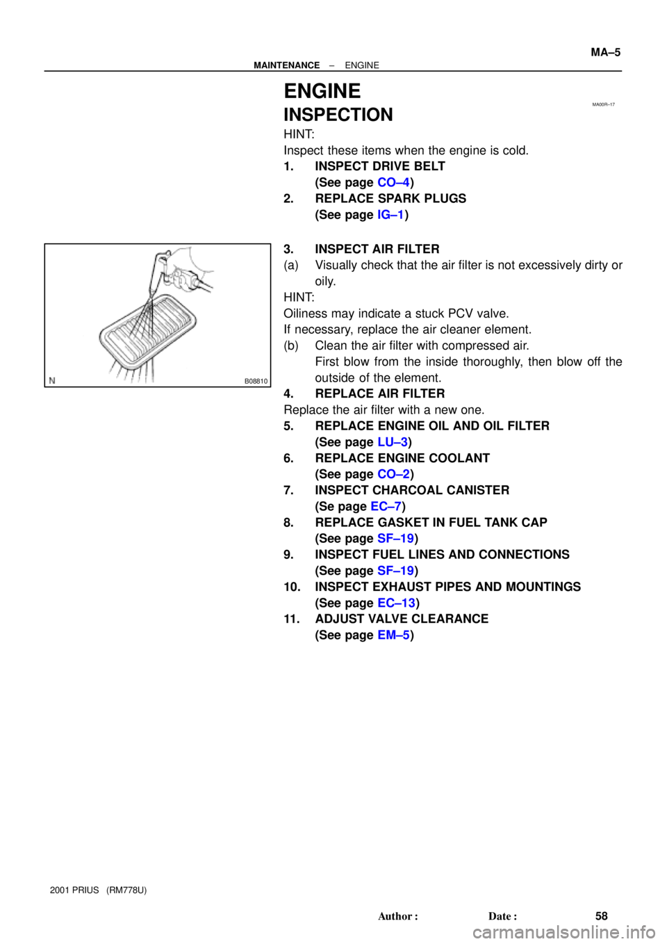
3. INSPECT AIR FILTER
(a) Visually check that the air filter is not excessively dirty or
oily.
HINT:
Oiliness may indicate a stuck PCV valve.
If necessary, replace the air cleaner element.
(b) Clean the air filter with compressed air.
First blow from the inside thoroughly, then blow off the
outside of the element.
4. REPLACE AIR FILTER
Replace the air filter with a new one.
5. REPLACE ENGINE OIL AND OIL FILTER
(See page LU±3)
6. REPLACE ENGINE COOLANT
(See page CO±2)
7. INSPECT CHARCOAL CANISTER
(Se page EC±7)
8. REPLACE GASKET IN FUEL TANK CAP
(See page SF±19)
9. INSPECT FUEL LINES AND CONNECTIONS
(See page SF±19)
10. INSPECT EXHAUST PIPES AND MOUNTINGS
(See page EC±13)
11. ADJUST VALVE CLEARANCE
(See page EM±5)
Page 1466 of 1943

COMPRESSION
INSPECTION
HINT:
If there is lack of power, excessi")
EM1IT±02
F12396
TOYOTA Hand±held
Tester
DLC3
A13923
± ENGINE MECHANICALCOMPRESSION
EM±3
111 9 Author�: Date�:
2001 PRIUS (RM778U)
COMPRESSION
INSPECTION
HINT:
If there is lack of power, excessive oil consumption or poor fuel
economy, measure the compression pressure.
NOTICE:
The measurement of compression pressure should be per-
formed in the Cranking Mode.
1. WARM UP AND STOP ENGINE
Allow the engine to warm up to normal operating temperature.
2. REMOVE AIR CLEANER ASSEMBLY
3. REMOVE IGNITION COIL (See page IG±6)
4. REMOVE SPARK PLUGS
5. CONNECT TOYOTA HAND±HELD TESTER
(a) Connect the TOYOTA hand±held tester to the DLC3.
(b) Select the cranking mode on the TOYOTA hand±held tes-
ter.
(c) Please refer TOYOTA hand±held tester operato's manual
for further details.
6. INSPECT CYLINDER COMPRESSION PRESSURE
(a) Insert a compression gauge into the spark plug hole.
(b) Fully open the throttle.
(c) While cranking the engine, measure the compression
pressure.
HINT:
In the Cranking Mode, the engine speed is automatically con-
trolled at 250 rpm and the throttle valve is also automatically set
in fully±opened condition.
(d) Repeat steps (a) through (c) for each cylinder.
NOTICE:
This measurement must be done in as short a time as pos-
sible.
Compression pressure:
728 kPa (7.4 kgf/cm
2, 106 psi)
Minimum pressure:
534 kPa (5.4 kgf/cm
2, 77 psi)
Difference between each cylinder:
98 kPa (1.0 kgf/cm
2, 14 psi) or less
Page 1467 of 1943
EM±4
± ENGINE MECHANICALCOMPRESSION
1120 Author�: Date�:
2001 PRIUS (RM778U)
(e) If the cylinder compression in one more cylinders is low,
pour a small amount of engine oil into the cylinder through
the spark plug hole and repeat steps (a) through (c) for
cylinders with low compression.
�If adding oil helps the compression, it is likely that
the piston rings and/or cylinder bore are worn or
damaged.
�If pressure stays low, a valve may be sticking or
seating is improper, or there may be leakage past
the gasket.
7. REINSTALL SPARK PLUGS
8. REINSTALL IGNITION COIL (See page IG±7)
Page 1488 of 1943

REMOVAL
1. DISCONNECT BATTERY NEGATIVE (± )TERMINAL
AND HV BATTERY SERVICE PLUG
(See page HV±1)
2. REMOV")
EM1IX±02
A13907
B11761
A13934
± ENGINE MECHANICALCYLINDER HEAD
EM±29
2001 PRIUS (RM778U)
REMOVAL
1. DISCONNECT BATTERY NEGATIVE (± )TERMINAL
AND HV BATTERY SERVICE PLUG
(See page HV±1)
2. REMOVE OUTER FRONT COWL TOP PANEL AS-
SEMBLY (See page BO±32)
3. DRAIN HV TRANSAXLE COOLANT
(See page HT±6)
4. DRAIN ENGINE COOLANT
5. REMOVE CONVERTER AND INVERTER ASSEMBLY
(See page HV±18)
6. REMOVE AIR CLEANER ASSEMBLY
(a) Disconnect the MAF meter connector.
(b) Disconnect the EVAP hose from the air cleaner case.
(c) Loosen the 2 hose clamps.
(d) Remove the 3 bolts and air cleaner assembly.
7. REMOVE IGNITION COILS (See page IG±6)
8. REMOVE SPARK PLUGS (See page IG±1)
9. REMOVE PCV HOSES
10. REMOVE THROTTLE BODY (See page SF±28)
11. DISCONNECT ENGINE WIRE FROM CYLINDER HEAD
(a) Disconnect the ECT sensor connector.
(b) Disconnect the camshaft position sensor connector.
(c) Disconnect the oil control valve connector.
(d) Disconnect the 4 injector connectors.
(e) Remove the 3 bolts and disconnect the engine wire pro-
tector from the cylinder head cover.
Page 1506 of 1943

16. INSTALL INTAKE MANIFOLD
Install a new gasket, the intake manifold and 2 brackets with the
2 bolts and 2 nuts. Un")
A13935
A13934
A13907
EM±48
± ENGINE MECHANICALCYLINDER HEAD
2001 PRIUS (RM778U)
16. INSTALL INTAKE MANIFOLD
Install a new gasket, the intake manifold and 2 brackets with the
2 bolts and 2 nuts. Uniformly tighten the bolts and nuts in sever-
al passes.
Torque: 20 N´m (204 kgf´cm, 15 ft´lbf)
17. CONNECT ENGINE WIRE TO CYLINDER HEAD
(a) Install the engine wire protector to the cylinder head cover
with the 2 bolts.
(b) Connect the water ECT sensor connector.
(c) Connect the camshaft position sensor connector.
(d) Connect the oil control valve connector.
(e) Connect the 4 injector connectors.
18. INSTALL THROTTLE BODY
(See page SF±31)
19. INSTALL PCV HOSES
20. INSTALL SPARK PLUGS
(See page IG±1)
21. INSTALL IGNITION COILS (See page IG±7)
22. INSTALL AIR CLEANER ASSEMBLY
(a) Install the air cleaner assembly with the 2 bolts.
(b) Tighten the 2 hose clamps.
(c) Connect the EVAP hose to the air cleaner case.
(d) Connect the MAF meter connector.
23. INSTALL CONVERTER AND INVERTER ASSEMBLY
(See page HV±18)
24. INSTALL OUTER FR COWL TOP PANEL ASSEMBLY
(See page BO±32)
25. FILL WITH ENGINE COOLANT
26. FILL WITH HV COOLANT
27. INSTALL ENGINE UNDER COVERS
28. CONNECT BATTERY NEGATIVE (±) TERMINAL AND
HV BATTERY SERVICE PLUG (See page HV±1)