Page 283 of 1943
NEW MODEL OUTLINE
2,550 (100.4)Short rear
overhang Short front
overhang
mm (in.)
4,305 (169.6)182MO02
Long wheelbase
CD = 0.29
attained!
Front tire fairingRear spoiler
Rear tire fairing
182MO03
182MO04
9
Side Design
A mono-form silhouette is the basis of the ultra modern side view.
�The short overhang adopted reflects the consideration given to minimize the turning radius.
And the long wheelbase brings better riding comfort and spacious cabin.
Aerodynamics
The upper body profile provides smooth airflow through the free use of computer simulation. Furthermore,
the front tire fairing, rear tire fairing, rear spoiler and flat under-body, among others achieve an excellent drag
coefficient of CD = 0.29.
Disc Wheel
Aluminum wheels are fitted standard on all models.
SizeDesign
P175/65 R14 5 1/2JJ
Page 601 of 1943

SS13W±06
SS±26
± SERVICE SPECIFICATIONSSUSPENSION AND AXLE
148 Author�: Date�:
2001 PRIUS (RM778U)
SUSPENSION AND AXLE
SERVICE DATA
Cold tire inflation
pressureTire size: P175/65R14 84S Front
Rear240 kPa (2.4 kgf/cm2, 35 psi)
230 kPa (2.3 kgf/cm2, 33 psi)
Vehicle height
P175/65R14Front*1
Rear*2191 mm (7.52 in.)
239 mm (9.41 in.)
Camber
Right±left error±0°26' ± 45' (±0.43° ± 0.75°)
45' (0.75°) or less
Front wheel
Caster
Right±left error1°02' ± 45' (1.03° ± 0.75°)
45' (0.75°) or less
Front wheel
alignmentSteering axis inclination
Right±left error9°52' ± 45' (9.87° ± 0.75°)
45' (0.75°) or less
Toe±in (total)
Rack end length difference0°06' ± 12' (0.1° ± 0.2°, 1 ± 2 mm, 0.04± 0.08 in.)
1.5 mm (0.059 in.) or less
Wheel angle
Inside wheel
Outside wheel: Reference
42°42' ± 2° (42.70° ± 2°)
35°54' (35.90°)
Rear wheel
Camber
Right±left error±1°30' ± 45' (±0.93° ± 0.75°)
45' (0.75°) or less
Rear wheel
alignmentToe±in (total)0°06' ± 20' (0.1° ± 0.33°)
1 ± 3.0 mm (0.04 ± 0.12 in.)
FtlAxle bearing backlash Maximum0.05 mm (0.0020 in.)Front axleAxle hub deviationMaximum0.07 mm (0.0028 in.)
Front drive shaftDrive shaft standard length LH
RH579.9 ± 5.0 mm (22.831 ± 0.197 in.)
836.9 ± 5.0 mm (32.949 ± 0.197 in.)
Ft iLower suspension arm ball joint turning torque1.0 ± 4.9 N´m (10 ± 50 kgf´cm, 8.7 ± 43 in.´lbf)Front suspensionStabilizer bar link ball joint turning torque0.05 ± 1.0 N´m (0.5 ± 10 kgf´cm, 0.4 ± 8.7 in.´lbf)
RlAxle bearing backlash Maximum0.05 mm (0.0020 in.)Rear axleAxle hub deviationMaximum0.07 mm (0.0028 in.)
*1: Front measuring point
Measure the distance from the ground to the head center of the front side lower suspension arm mounting
bolt.
*2: Rear measuring point
Measure the distance from the ground to the center of the rear axle beam mounting bolt.
Page 1654 of 1943

SA0CC±10
R03031
R15157
Front
R07928
R14731
Backlash:Deviation: SA±2
± SUSPENSION AND AXLETIRE AND WHEEL
1452 Author�: Date�:
2001 PRIUS (RM778U)
TIRE AND WHEEL
INSPECTION
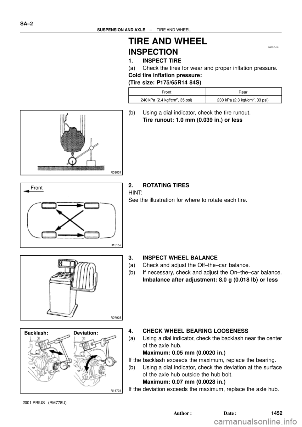
1. INSPECT TIRE
(a) Check the tires for wear and proper inflation pressure.
Cold tire inflation pressure:
(Tire size: P175/65R14 84S)
FrontRear
240 kPa (2.4 kgf/cm2, 35 psi)230 kPa (2.3 kgf/cm2, 33 psi)
(b) Using a dial indicator, check the tire runout.
Tire runout: 1.0 mm (0.039 in.) or less
2. ROTATING TIRES
HINT:
See the illustration for where to rotate each tire.
3. INSPECT WHEEL BALANCE
(a) Check and adjust the Off±the±car balance.
(b) If necessary, check and adjust the On±the±car balance.
Imbalance after adjustment: 8.0 g (0.018 lb) or less
4. CHECK WHEEL BEARING LOOSENESS
(a) Using a dial indicator, check the backlash near the center
of the axle hub.
Maximum: 0.05 mm (0.0020 in.)
If the backlash exceeds the maximum, replace the bearing.
(b) Using a dial indicator, check the deviation at the surface
of the axle hub outside the hub bolt.
Maximum: 0.07 mm (0.0028 in.)
If the deviation exceeds the maximum, replace the axle hub.
Page 1776 of 1943

I17791
0.4 °
3 m (9.84 ft) H 29.7 mm
(1.17 in.)
7
V RH Line
W90 °
V LH Line4
Low Beam:
V LH LineV Line V RH Line 65
6
29.7 mm
(1.17 in.)
High Beam:
V LH LineV Line V RH Line 6
5629.7 mm
(1.17 in.)
29.7 mm
(1.17 in.) H 4
O: step No.
7
H4
W
W
± BODY ELECTRICALHEADLIGHT AND TAILLIGHT SYSTEM
BE±23
2001 PRIUS (RM778U)
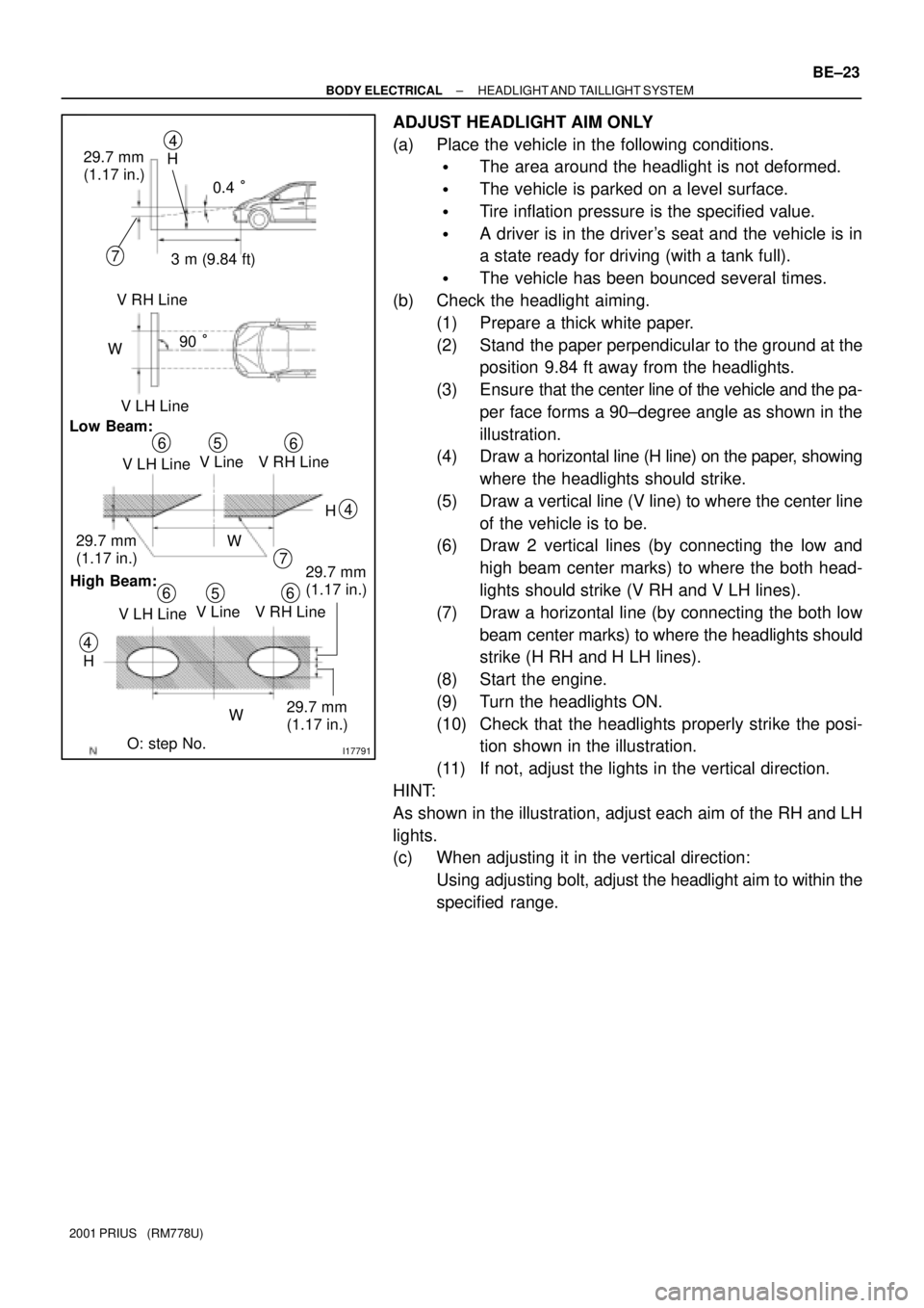
ADJUST HEADLIGHT AIM ONLY
(a) Place the vehicle in the following conditions.
�The area around the headlight is not deformed.
�The vehicle is parked on a level surface.
�Tire inflation pressure is the specified value.
�A driver is in the driver's seat and the vehicle is in
a state ready for driving (with a tank full).
�The vehicle has been bounced several times.
(b) Check the headlight aiming.
(1) Prepare a thick white paper.
(2) Stand the paper perpendicular to the ground at the
position 9.84 ft away from the headlights.
(3) Ensure that the center line of the vehicle and the pa-
per face forms a 90±degree angle as shown in the
illustration.
(4) Draw a horizontal line (H line) on the paper, showing
where the headlights should strike.
(5) Draw a vertical line (V line) to where the center line
of the vehicle is to be.
(6) Draw 2 vertical lines (by connecting the low and
high beam center marks) to where the both head-
lights should strike (V RH and V LH lines).
(7) Draw a horizontal line (by connecting the both low
beam center marks) to where the headlights should
strike (H RH and H LH lines).
(8) Start the engine.
(9) Turn the headlights ON.
(10) Check that the headlights properly strike the posi-
tion shown in the illustration.
(11) If not, adjust the lights in the vertical direction.
HINT:
As shown in the illustration, adjust each aim of the RH and LH
lights.
(c) When adjusting it in the vertical direction:
Using adjusting bolt, adjust the headlight aim to within the
specified range.
Page 1788 of 1943

I18205
I18205
± BODY ELECTRICALCOMBINATION METER
BE±43
2001 PRIUS (RM778U) A22 ± Ground
(IG ± Body ground)
Ignition switch OFF or ONBelow 1V or 10 ± 14 V
B1 ± Ground
(ROUT ± Body ground)Ignition switch ON and shift lever position is ºRº
or except ºRºBelow 1V or 10 ± 14 V
B2 ± Ground
(MPX+ ± Body ground)Ignition switch ONPulse generation
B3 ± Ground
(MPX ± Body ground)Ignition switch ONPulse generation
B5 ± Ground
(ACC ± Body ground)Ignition switch ACC10 ± 14 V
2. INSPECT SPEEDOMETER ON±VEHICLE
Using a speedometer tester, inspect the speedometer for allow-
able indication error and check the operation of the odometer.
HINT:
Tire wear and tire over or under inflation will increase the indica-
tion error.
If error is excessive, replace the speedometer.
(mph)(km/h)
Standard indication Allowable rangeStandard indication Allowable range
20 18± 22 20 18 ± 22
40 38 ± 42 40 38 ± 42
60 59 ± 63 60 58 ± 62
80 79 ± 83 80 78 ± 82
100 99 ± 104 100 97 ± 103
120 119 ± 125 120 117 ± 123
140 137 ± 143
160 157 ± 163
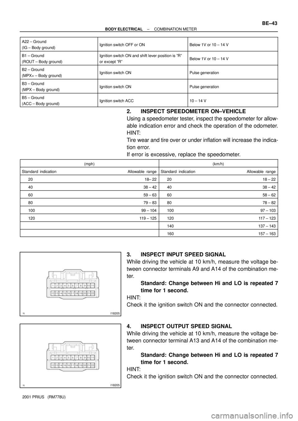
3. INSPECT INPUT SPEED SIGNAL
While driving the vehicle at 10 km/h, measure the voltage be-
tween connector terminals A9 and A14 of the combination me-
ter.
Standard: Change between Hi and LO is repeated 7
time for 1 second.
HINT:
Check it the ignition switch ON and the connector connected.
4. INSPECT OUTPUT SPEED SIGNAL
While driving the vehicle at 10 km/h, measure the voltage be-
tween connector terminal A13 and A14 of the combination me-
ter.
Standard: Change between Hi and LO is repeated 7
time for 1 second.
HINT:
Check it the ignition switch ON and the connector connected.