2001 TOYOTA PRIUS parking brake
[x] Cancel search: parking brakePage 8 of 1943
2001 PRIUS (EWD414U)
B HOW TO USE THIS MANUAL
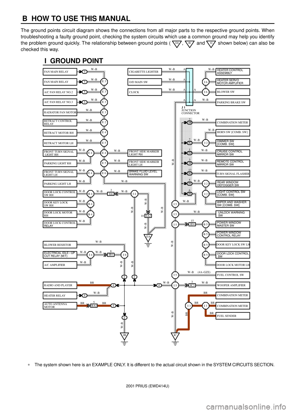
The ground points circuit diagram shows the connections from all major parts to the respective ground points. When
troubleshooting a faulty ground point, checking the system circuits which use a common ground may help you identify
the problem ground quickly. The relationship between ground points (
EA, IB and IC shown below) can also be
checked this way.
I GROUND POINT
FAN MAIN RELAY
FAN MAIN RELAY
A/C FAN RELAY NO.2
A/C FAN RELAY NO.3
RADIATOR FAN MOTOR
RETRACT CONTROL
RELAY
RETRACT MOTOR RH
RETRACT MOTOR LH
FRONT TURN SIGNAL
LIGHT RH
PARKING LIGHT RH
FRONT TURN SIGNAL
LIGHT LH
PARKING LIGHT LH
DOOR LOCK CONTROL
SW RH
DOOR KEY LOCK
SW RH
DOOR LOCK MOTOR
RH
BLOWER RESISTOR
A/C AMPLIFIER
RADIO AND PLAYER
HEATER RELAY
AUTO ANTENNA
MOTOR
BLOWER SW
PARKING BRAKE SW
COMBINATION METER
HORN SW [COMB. SW]
TURN SIGNAL FLASHER
DOOR KEY LOCK SW LH
DOOR LOCK MOTOR LH
FUEL CONTROL SW
WOOFER AMPLIFIER
COMBINATION METER
COMBINATION METER
FUEL SENDER
CIGARETTE LIGHTER
O/D MAIN SW
CLOCK
5
5
5
5
4
4
4
4
4BA15
IB18
EA2 10
3E5
3E
6 3G
13 3F
3 3D
1 3B
7
ID115
IC33
IA12
E 3
A
A AW±B
W±BW±B W±B
W±B W±B
W±B
W±B
W±B
W±B
W±B
W±B
W±B
W±B
W±B W±BW±B W±B W±B W±B
W±B W±B
W±BW±B
W±B
W±B
W±B W±B
W±B
BR
W±B
BR BRW±BW±B
W±B
W±B
W±B
W±B
W±B
W±B
W±B
W±B
W±B W±B
W±B
W±B
W±B
W±B
BR W±B
BR BR
BR W±B W±BW±B
W±BW±BBR W±B (4A±GZE)
W±B A A A
I 6
I 6
I 2
I 2
I 2
B 5I 5
I 5
I 5
B 5
B 5
B 5
I 5
I 5
I 3I 3
E 3
E 3
E 3
E 2
E 4
E 5
E 4
E 5
E 6E 4
E 4
B 4
EAI 4
B 4
B 4
I 4I 8
IBIC
3C7
4
JUNCTION
CONNECTOR J 1
4
DOOR LOCK CONTROL
RELAY
ELECTRICAL IDLE-UP
CUT RELAY (M/T)FRONT SIDE MARKER
LIGHT RH
FRONT SIDE MARKER
LIGHT LH
BRAKE FLUID LEVEL
WARNING SW
UNLOCK WARNING
SW WIPER AND WASHER
SW [COMB. SW] LIGHT CONTROL SW
[COMB. SW] HEATER CONTROL
ASSEMBLY
HEATER SERVO
MOTOR AMPLIFIER
DIMMER SW
[COMB. SW]
CRUISE CONTROL
MIRROR SW
REAR WINDOW
DEFOGGER SW
POWER WINDOW
MASTER SW
POWER WINDOW
CONTROL RELAY
DOOR LOCK CONTROL
SW
REMOTE CONTROL
MIRROR SW
*The system shown here is an EXAMPLE ONLY. It is different to the actual circuit shown in the SYSTEM CIRCUITS SECTION.
Page 34 of 1943

2001 PRIUS (EWD414U)
G ELECTRICAL WIRING ROUTING
Position of Parts in Engine Compartment
A 1 A/C Condenser Fan Motor
A 2 A/C Magnetic Clutch and Lock Sensor
A 3 A/C Triple Pressure SW
(A/C Dual and Single Pressure SW)
A 4 ABS Speed Sensor Front LH
A 5 ABS Speed Sensor Front RH
A 6 Ambient Temp. Sensor
B 1 Brake Actuator
B 2 Brake Actuator
B 3 Brake Actuator
B 4 Brake Fluid Level Warning SW
C 1 Camshaft Position Sensor
C 2 Camshaft Timing Oil Control Valve
C 3 Circuit Breaker Sensor
C 4 Converter
C 5 Converter
C 6 Crankshaft Position Sensor
D 1 DC Motor
E 1 Engine Coolant Temp. Sensor
E 2 Engine Hood Courtesy SWF 1 Front Airbag Sensor LH
F 2 Front Airbag Sensor RH
F 3 Front Parking Light LH
F 4 Front Parking Light RH
F 5 Front Side Marker Light LH
F 6 Front Side Marker Light RH
F 7 Front Turn Signal Light LH
F 8 Front Turn Signal Light RH
F 9 Front Wiper Motor
F 10 Fusible Link Block No.1
F 11 Fusible Link Block No.1
F 12 Fusible Link Block No.1
F 13 Fusible Link Block No.1
H 1 Headlight LH
H 2 Headlight RH
H 3 Heated Oxygen Sensor (Bank 1 Sensor1)
H 4 Horn
H 5 Hydraulic Booster
H 6 Hydraulic Booster
Page 37 of 1943

2001 PRIUS (EWD414U)
G
Position of Parts in Instrument Panel
G 1 Gateway ECU
H 7 Hazard Warning SW
H 8 Hazard Warning SW
H 9 Heated Oxygen Sensor (Bank 1 Sensor 2)
H 10 Hybrid Vehicle Control ECU
H 11 Hybrid Vehicle Control ECU
H 12 Hybrid Vehicle Control ECU
H 13 Hybrid Vehicle Control ECU
H 14 Hybrid Vehicle Control ECU
I 15 Ignition SW
J 1 Junction Connector
J 2 Junction Connector
J 3 Junction Connector
J 4 Junction Connector
J 5 Junction Connector
J 6 Junction Connector
J 7 Junction Connector
J 8 Junction Connector
J 9 Junction Connector
J 10 Junction Connector
J 11 Junction Connector
J 12 Junction Connector
J 13 Junction Connector
J 14 Junction Connector
J 15 Junction Connector
J 16 Junction Connector
J 17 Junction Connector
J 18 Junction Connector
J 19 Junction Connector
J 20 Junction Connector
J 21 Junction ConnectorJ 22 Junction Connector
J 23 Junction Connector
J 24 Junction Connector
J 25 Junction Connector
J 26 Junction Connector
J 27 Junction Connector
J 28 Junction Connector
J 29 Junction Connector
L 1 Light Control Rheostat
M 5 Multi Display
M 6 Multi Display
M 7 Multi Display
P 1 Park/Neutral Position SW
P 2 Parking Brake SW
P 3 PTC Heater
P 4 PTC Heater
R 2 Radio and Player
R 3 Radio and Player
R 4 Radio and Player
R 5 Remote Control Mirror SW
S 2 Shift Lock ECU
S 3 Stop Light SW
T 4 Transponder Key Computer
T 5 Turn Signal Flasher Relay
U 1 Unlock Warning SW and Key Interlock Solenoid
W 5 Wireless Door Control Receiver
Page 50 of 1943
2001 PRIUS (EWD414U)
POWER SOURCE
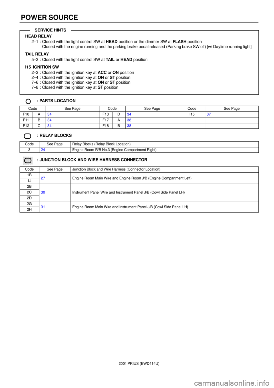
HEAD RELAY
2±1 : Closed with the light control SW at HEAD position or the dimmer SW at FLASH position
Closed with the engine running and the parking brake pedal released (Parking brake SW off) [w/ Daytime running light]
TAIL RELAY
5±3 : Closed with the light control SW at TAIL or HEAD position
I15 IGNITION SW
2±3 : Closed with the ignition key at ACC or ON position
2±4 : Closed with the ignition key at ON or ST position
7±6 : Closed with the ignition key at ON or ST position
7±8 : Closed with the ignition key at ST position
: PARTS LOCATION
CodeSee PageCodeSee PageCodeSee Page
F10A34F13D34I1537
F11B34F17A38
F12C34F18B38
: RELAY BLOCKS
CodeSee PageRelay Blocks (Relay Block Location)
324Engine Room R/B No.3 (Engine Compartment Right)
: JUNCTION BLOCK AND WIRE HARNESS CONNECTOR
CodeSee PageJunction Block and Wire Harness (Connector Location)
1B27Engine Room Main Wire and Engine Room J/B (Engine Compartment Left)1J27Engine Room Main Wire and Engine Room J/B (Engine Compartment Left)
2B
2C30Instrument Panel Wire and Instrument Panel J/B (Cowl Side Panel LH)
2D
()
2G31Engine Room Main Wire and Instrument Panel J/B (Cowl Side Panel LH)2H31Engine Room Main Wire and Instrument Panel J/B (Cowl Side Panel LH)
SERVICE HINTS
Page 79 of 1943
2001 PRIUS (EWD414U)
2B 62A 7 10 2A72I
ID OFF
TAIL
HEAD
LOW
HIGH
IG ID2 510A
GAUGE FROM POWER SOURCE SYSTEM (
SEE PAGE 50)
2K 10
B E
A E
1ID2 7 7. 5A
ECU±B
2C 5
ID1 8
IA2 16
DAYTIME RUNNING LIGHT RELAY D 3
JUNCTION
CONNECTOR J20JUNCTION
CONNECTOR J2 0
JUNCTION
CONNECTOR J17
JUNCTION
CONNECTOR J1 1
PARKING
BRAKE SW P 2
COMBINATION SW C13 DIODE
(
DAYTIME
RUNNING
LIGHT) D 5 1
EE46 3 12AC
87
A17 2
E17 8 11 92 5AC
14
R±W
R±G
R±L R±G R±G
R±L R±W RR±GR±G
L±O
R±Y
Y±B
W±B
R±G L Y±B R±Y
BRW±B
L
R±BL R±G R±W
R R±G R±G
R±W
W±B
EDRL HDIM H±LP +B IG
HI PKB CHG± IND
ID2 3
13 16
JUNCTION CONNECTORB J12 A , J13
B 2
B 17 A9 BODY ECUB B 8 , B 9A
Y±BA F
B HR±G
R±G
JUNCTION
CONNECTORB J27 A , J28
E
FLASH
LIGHT
CONTROL SW DIMMER SW
15A
DOME
1J 7
HIGH BEAM
HEAD
42A 22G
LL±Y
21
COMBINATION METER C10L±Y
H RDY HRLY
IH
Page 80 of 1943
2001 PRIUS (EWD414U)
HEADLIGHT (w/ DAYTIME RUNNING LIGHT)
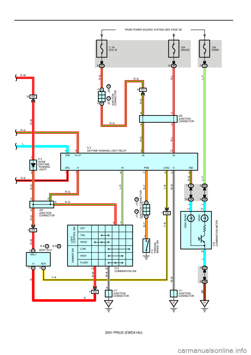
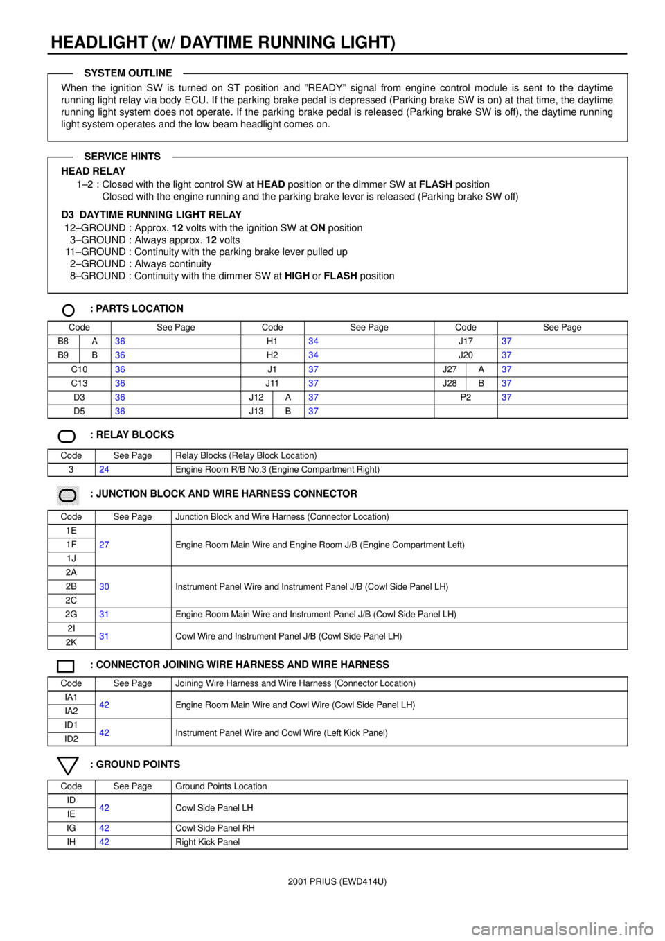
When the ignition SW is turned on ST position and ºREADYº signal from engine control module is sent to the daytime
running light relay via body ECU. If the parking brake pedal is depressed (Parking brake SW is on) at that time, the daytime
running light system does not operate. If the parking brake pedal is released (Parking brake SW is off), the daytime running
light system operates and the low beam headlight comes on.
HEAD RELAY
1±2 : Closed with the light control SW at HEAD position or the dimmer SW at FLASH position
Closed with the engine running and the parking brake lever is released (Parking brake SW off)
D3 DAYTIME RUNNING LIGHT RELAY
12±GROUND : Approx. 12 volts with the ignition SW at ON position
3±GROUND : Always approx. 12 volts
11±GROUND : Continuity with the parking brake lever pulled up
2±GROUND : Always continuity
8±GROUND : Continuity with the dimmer SW at HIGH or FLASH position
: PARTS LOCATION
CodeSee PageCodeSee PageCodeSee Page
B8A36H134J1737
B9B36H234J2037
C1036J137J27A37
C1336J1137J28B37
D336J12A37P237
D536J13B37
: RELAY BLOCKS
CodeSee PageRelay Blocks (Relay Block Location)
324Engine Room R/B No.3 (Engine Compartment Right)
: JUNCTION BLOCK AND WIRE HARNESS CONNECTOR
CodeSee PageJunction Block and Wire Harness (Connector Location)
1E
1F27Engine Room Main Wire and Engine Room J/B (Engine Compartment Left)
1J
gg(g)
2A
2B30Instrument Panel Wire and Instrument Panel J/B (Cowl Side Panel LH)
2C
()
2G31Engine Room Main Wire and Instrument Panel J/B (Cowl Side Panel LH)
2I31Cowl Wire and Instrument Panel J/B (Cowl Side Panel LH)2K31Cowl Wire and Instrument Panel J/B (Cowl Side Panel LH)
: CONNECTOR JOINING WIRE HARNESS AND WIRE HARNESS
CodeSee PageJoining Wire Harness and Wire Harness (Connector Location)
IA142Engine Room Main Wire and Cowl Wire (Cowl Side Panel LH)IA242Engine Room Main Wire and Cowl Wire (Cowl Side Panel LH)
ID142Instrument Panel Wire and Cowl Wire (Left Kick Panel)ID242Instrument Panel Wire and Cowl Wire (Left Kick Panel)
: GROUND POINTS
CodeSee PageGround Points Location
ID42Cowl Side Panel LHIE42Cowl Side Panel LH
IG42Cowl Side Panel RH
IH42Right Kick Panel
SYSTEM OUTLINE
SERVICE HINTS
Page 103 of 1943
2001 PRIUS (EWD414U)
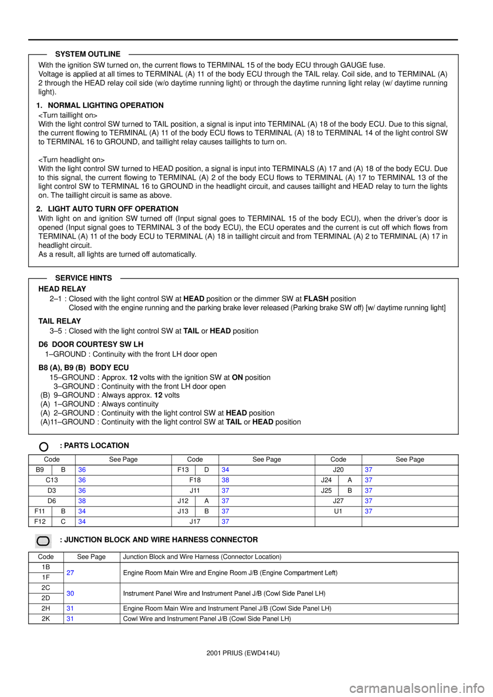
With the ignition SW turned on, the current flows to TERMINAL 15 of the body ECU through GAUGE fuse.
Voltage is applied at all times to TERMINAL (A) 11 of the body ECU through the TAIL relay. Coil side, and to TERMINAL (A)
2 through the HEAD relay coil side (w/o daytime running light) or through the daytime running light relay (w/ daytime running
light).
1. NORMAL LIGHTING OPERATION
With the light control SW turned to TAIL position, a signal is input into TERMINAL (A) 18 of the body ECU. Due to this signal,
the current flowing to TERMINAL (A) 11 of the body ECU flows to TERMINAL (A) 18 to TERMINAL 14 of the light control SW
to TERMINAL 16 to GROUND, and taillight relay causes taillights to turn on.
With the light control SW turned to HEAD position, a signal is input into TERMINALS (A) 17 and (A) 18 of the body ECU. Due
to this signal, the current flowing to TERMINAL (A) 2 of the body ECU flows to TERMINAL (A) 17 to TERMINAL 13 of the
light control SW to TERMINAL 16 to GROUND in the headlight circuit, and causes taillight and HEAD relay to turn the lights
on. The taillight circuit is same as above.
2. LIGHT AUTO TURN OFF OPERATION
With light on and ignition SW turned off (Input signal goes to TERMINAL 15 of the body ECU), when the driver's door is
opened (Input signal goes to TERMINAL 3 of the body ECU), the ECU operates and the current is cut off which flows from
TERMINAL (A) 11 of the body ECU to TERMINAL (A) 18 in taillight circuit and from TERMINAL (A) 2 to TERMINAL (A) 17 in
headlight circuit.
As a result, all lights are turned off automatically.
HEAD RELAY
2±1 : Closed with the light control SW at HEAD position or the dimmer SW at FLASH position
Closed with the engine running and the parking brake lever released (Parking brake SW off) [w/ daytime running light]
TAIL RELAY
3±5 : Closed with the light control SW at TAIL or HEAD position
D6 DOOR COURTESY SW LH
1±GROUND : Continuity with the front LH door open
B8 (A), B9 (B) BODY ECU
15±GROUND : Approx. 12 volts with the ignition SW at ON position
3±GROUND : Continuity with the front LH door open
(B) 9±GROUND : Always approx. 12 volts
(A) 1±GROUND : Always continuity
(A) 2±GROUND : Continuity with the light control SW at HEAD position
(A)11±GROUND : Continuity with the light control SW at TAIL or HEAD position
: PARTS LOCATION
CodeSee PageCodeSee PageCodeSee Page
B9B36F13D34J2037
C1336F1838J24A37
D336J1137J25B37
D638J12A37J2737
F11B34J13B37U137
F12C34J1737
: JUNCTION BLOCK AND WIRE HARNESS CONNECTOR
CodeSee PageJunction Block and Wire Harness (Connector Location)
1B27Engine Room Main Wire and Engine Room J/B (Engine Compartment Left)1F27Engine Room Main Wire and Engine Room J/B (Engine Compartment Left)
2C30Instrument Panel Wire and Instrument Panel J/B (Cowl Side Panel LH)2D30Instrument Panel Wire and Instrument Panel J/B (Cowl Side Panel LH)
2H31Engine Room Main Wire and Instrument Panel J/B (Cowl Side Panel LH)
2K31Cowl Wire and Instrument Panel J/B (Cowl Side Panel LH)
SYSTEM OUTLINE
SERVICE HINTS
Page 154 of 1943
2001 PRIUS (EWD414U)
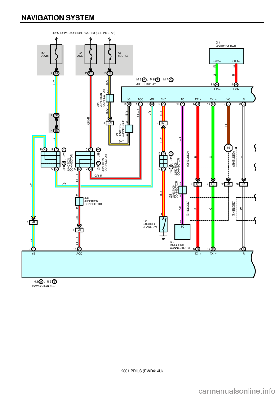
NAVIGATION SYSTEM
15A
DOMEFROM POWER SOURCE SYSTEM (
SEE PAGE 50)
1J 710A
ACC
2D 2
A 18 A 910 B B 5
L±Y
GR ±R
R
G GR±R L±Y
+B ACCTX1+ TX1 ± 2G 2
2D 4
L±Y
B CA CJUNCTION
CONNECTORB J27 A , J28
L±Y
L±Y GR±R
GR±R
NAVIGATION ECUB N 2 , N 3AB C A BAB
JUNCTION
CONNECTORB J24 A , J25
AM 6, M 5 B
MULTI DISPLAYC , M 7
C 1 C 4B5B10
B C
IJ1 4 IJ1 1
GR±R GR±RL±Y
B
BJUNCTION
CONNECTOR J26IJ1 6IJ17IJ1226B
IJ1 16
2B
R B 2
W R
G
W(
SHIELDED)
(
SHIELDED) (
SHIELDED)
(
SHIELDED)
5A
ECU±IG
2I 2
ID1 5C 2
P±B
14 A
P±B
D
D
E D
D
E
JUNCTION
CONNECTOR J14
JUNCTION
CONNECTOR J21
JUNCTION
CONNECTOR J26B±Y B±Y
B±Y
B±Y11 A A4 12 5
G
R
GATEWAY ECU G 1
A 13
ID1 7
B E
A E
1
R±Y R±Y R±Y
PARKING
BRAKE SW P 2
JUNCTION
CONNECTORB J12 A , J13
I 5
BR
13
TC
DATA LINK
CONNECTOR 3 D 2 IG ACC +B1 PKB TC TX1+ TX1± VG RTX3 ± TX3+ GTX± GTX+