Page 8 of 1943

2001 PRIUS (EWD414U)
B HOW TO USE THIS MANUAL
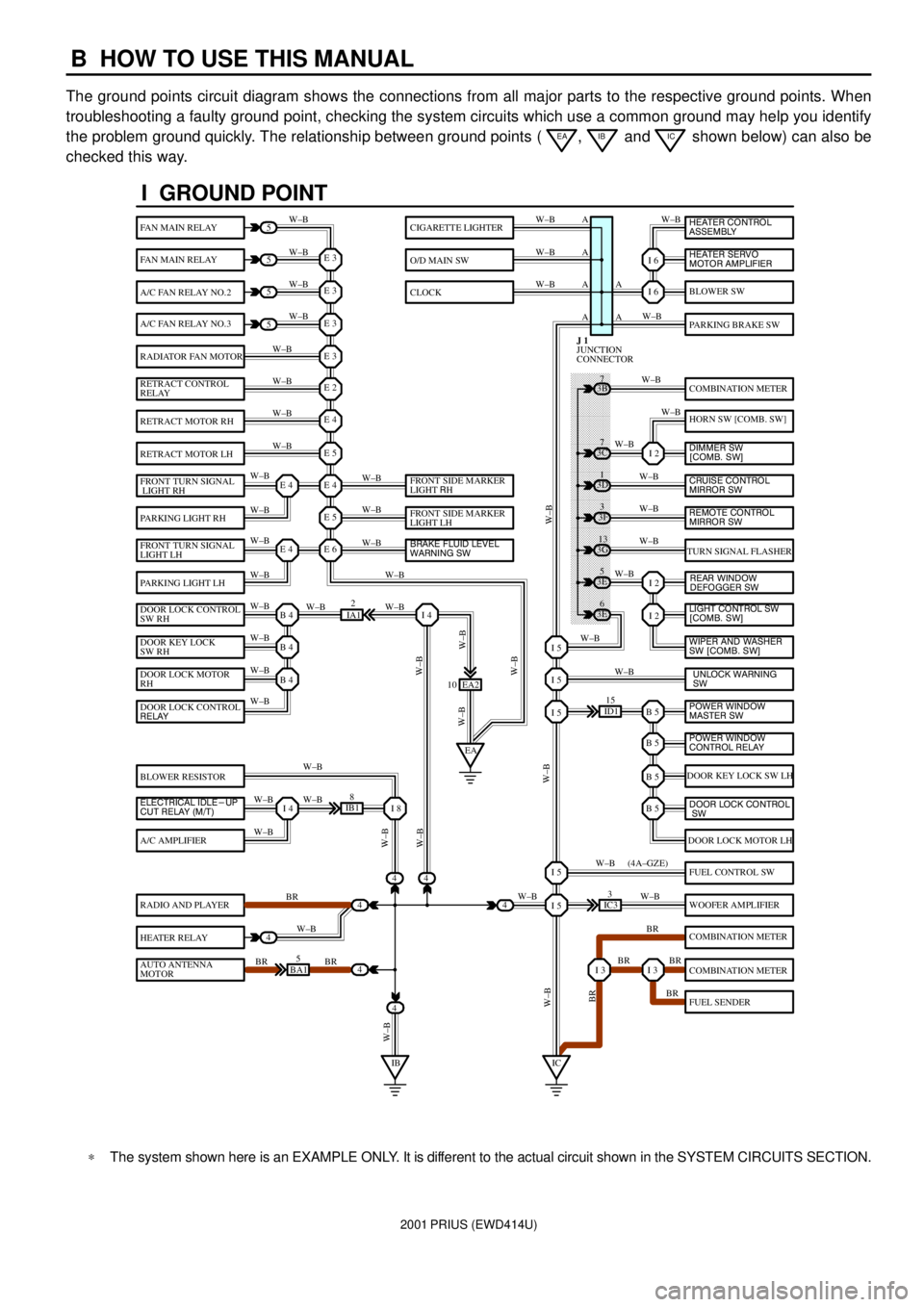
The ground points circuit diagram shows the connections from all major parts to the respective ground points. When
troubleshooting a faulty ground point, checking the system circuits which use a common ground may help you identify
the problem ground quickly. The relationship between ground points (
EA, IB and IC shown below) can also be
checked this way.
���� ���� ���� ���� ���� ���� ���� ���� ���� ���� ���� ���� ���� ���� ���� ���� ���� ���� ����
I GROUND POINT
FAN MAIN RELAY
FAN MAIN RELAY
A/C FAN RELAY NO.2
A/C FAN RELAY NO.3
RADIATOR FAN MOTOR
RETRACT CONTROL
RELAY
RETRACT MOTOR RH
RETRACT MOTOR LH
FRONT TURN SIGNAL
LIGHT RH
PARKING LIGHT RH
FRONT TURN SIGNAL
LIGHT LH
PARKING LIGHT LH
DOOR LOCK CONTROL
SW RH
DOOR KEY LOCK
SW RH
DOOR LOCK MOTOR
RH
BLOWER RESISTOR
A/C AMPLIFIER
RADIO AND PLAYER
HEATER RELAY
AUTO ANTENNA
MOTOR
BLOWER SW
PARKING BRAKE SW
COMBINATION METER
HORN SW [COMB. SW]
TURN SIGNAL FLASHER
DOOR KEY LOCK SW LH
DOOR LOCK MOTOR LH
FUEL CONTROL SW
WOOFER AMPLIFIER
COMBINATION METER
COMBINATION METER
FUEL SENDER
CIGARETTE LIGHTER
O/D MAIN SW
CLOCK
5
5
5
5
4
4
4
4
4BA15
IB18
EA2 10
3E5
3E
6 3G
13 3F
3 3D
1 3B
7
ID115
IC33
IA12
E 3
A
A AW±B
W±BW±B W±B
W±B W±B
W±B
W±B
W±B
W±B
W±B
W±B
W±B
W±B
W±B W±BW±B W±B W±B W±B
W±B W±B
W±BW±B
W±B
W±B
W±B W±B
W±B
BR
W±B
BR BRW±BW±B
W±B
W±B
W±B
W±B
W±B
W±B
W±B
W±B
W±B W±B
W±B
W±B
W±B
W±B
BR W±B
BR BR
BR W±B W±BW±B
W±BW±BBR W±B (4A±GZE)
W±B A A A
I 6
I 6
I 2
I 2
I 2
B 5I 5
I 5
I 5
B 5
B 5
B 5
I 5
I 5
I 3I 3
E 3
E 3
E 3
E 2
E 4
E 5
E 4
E 5
E 6E 4
E 4
B 4
EAI 4
B 4
B 4
I 4I 8
IBIC
3C7
4
JUNCTION
CONNECTOR J 1
4
DOOR LOCK CONTROL
RELAY
ELECTRICAL IDLE-UP
CUT RELAY (M/T)FRONT SIDE MARKER
LIGHT RH
FRONT SIDE MARKER
LIGHT LH
BRAKE FLUID LEVEL
WARNING SW
UNLOCK WARNING
SW WIPER AND WASHER
SW [COMB. SW] LIGHT CONTROL SW
[COMB. SW] HEATER CONTROL
ASSEMBLY
HEATER SERVO
MOTOR AMPLIFIER
DIMMER SW
[COMB. SW]
CRUISE CONTROL
MIRROR SW
REAR WINDOW
DEFOGGER SW
POWER WINDOW
MASTER SW
POWER WINDOW
CONTROL RELAY
DOOR LOCK CONTROL
SW
REMOTE CONTROL
MIRROR SW
*The system shown here is an EXAMPLE ONLY. It is different to the actual circuit shown in the SYSTEM CIRCUITS SECTION.
Page 34 of 1943

2001 PRIUS (EWD414U)
G ELECTRICAL WIRING ROUTING
Position of Parts in Engine Compartment
A 1 A/C Condenser Fan Motor
A 2 A/C Magnetic Clutch and Lock Sensor
A 3 A/C Triple Pressure SW
(A/C Dual and Single Pressure SW)
A 4 ABS Speed Sensor Front LH
A 5 ABS Speed Sensor Front RH
A 6 Ambient Temp. Sensor
B 1 Brake Actuator
B 2 Brake Actuator
B 3 Brake Actuator
B 4 Brake Fluid Level Warning SW
C 1 Camshaft Position Sensor
C 2 Camshaft Timing Oil Control Valve
C 3 Circuit Breaker Sensor
C 4 Converter
C 5 Converter
C 6 Crankshaft Position Sensor
D 1 DC Motor
E 1 Engine Coolant Temp. Sensor
E 2 Engine Hood Courtesy SWF 1 Front Airbag Sensor LH
F 2 Front Airbag Sensor RH
F 3 Front Parking Light LH
F 4 Front Parking Light RH
F 5 Front Side Marker Light LH
F 6 Front Side Marker Light RH
F 7 Front Turn Signal Light LH
F 8 Front Turn Signal Light RH
F 9 Front Wiper Motor
F 10 Fusible Link Block No.1
F 11 Fusible Link Block No.1
F 12 Fusible Link Block No.1
F 13 Fusible Link Block No.1
H 1 Headlight LH
H 2 Headlight RH
H 3 Heated Oxygen Sensor (Bank 1 Sensor1)
H 4 Horn
H 5 Hydraulic Booster
H 6 Hydraulic Booster
Page 507 of 1943

MA02E±02
± MAINTENANCEOUTSIDE VEHICLE
MA±1
54 Author�: Date�:
2001 PRIUS (RM778U)
OUTSIDE VEHICLE
GENERAL MAINTENANCE
These are maintenance and inspection items which are considered to be the owner's responsibility.
They can be done by the owner or they can have them done at a service shop.
These items include those which should be checked on a daily basis, those which, in most cases, do not
require (special) tools and those which are considered to be reasonable for the owner to do.
Items and procedures for general maintenance are as follows.
1. GENERAL NOTES
�Maintenance items may vary from country to country. Check the owner's manual supplement in which
the maintenance schedule is shown.
�Every service item in the periodic maintenance schedule must be performed.
�Periodic maintenance service must be performed according to whichever interval in the periodic main-
tenance schedule occurs first, the odometer reading (miles) or the time interval (months).
�Maintenance service after the last period should be performed at the same interval as before unless
otherwise noted.
�Failure to do even one item an cause the engine to run poorly and increase exhaust emissions.
2. TIRES
(a) Check the pressure with a gauge. If necessary, adjust.
(b) Check for cuts, damage or excessive wear.
3. WHEEL NUTS
When checking the tires, check the nuts for looseness or for missing nuts. If necessary, tighten them.
4. TIRE ROTATION
Check the owner's manual supplement in which the maintenance schedule is shown.
5. WINDSHIELD WIPER BLADES
Check for wear or cracks whenever they do not wipe clean. If necessary, replace.
6. FLUID LEAKS
Check underneath for leaking fuel, oil, water or other fluid.
7. DOORS AND ENGINE HOOD
(a) Check that all doors including the trunk lid operate smoothly, and that all latches lock securely.
(b) Check that the engine hood secondary latch secures the hood from opening when the primary latch
is released.
Page 1763 of 1943

BE±6
± BODY ELECTRICALTROUBLESHOOTING
1673 Author�: Date�:
2001 PRIUS (RM778U)
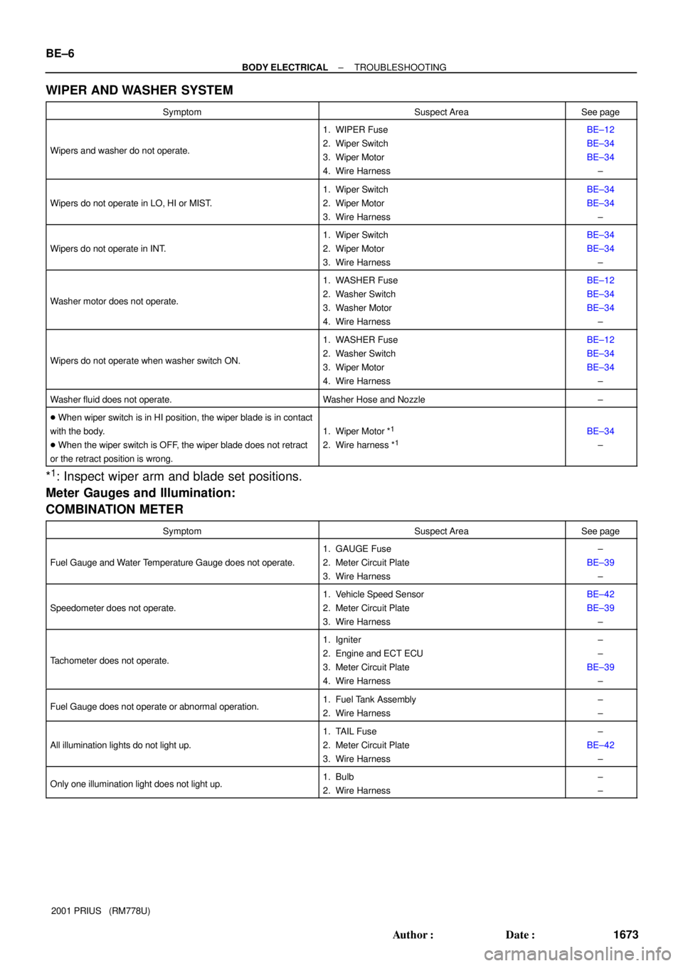
WIPER AND WASHER SYSTEM
SymptomSuspect AreaSee page
Wipers and washer do not operate.
1. WIPER Fuse
2. Wiper Switch
3. Wiper Motor
4. Wire HarnessBE±12
BE±34
BE±34
±
Wipers do not operate in LO, HI or MIST.
1. Wiper Switch
2. Wiper Motor
3. Wire HarnessBE±34
BE±34
±
Wipers do not operate in INT.
1. Wiper Switch
2. Wiper Motor
3. Wire HarnessBE±34
BE±34
±
Washer motor does not operate.
1. WASHER Fuse
2. Washer Switch
3. Washer Motor
4. Wire HarnessBE±12
BE±34
BE±34
±
Wipers do not operate when washer switch ON.
1. WASHER Fuse
2. Washer Switch
3. Wiper Motor
4. Wire HarnessBE±12
BE±34
BE±34
±
Washer fluid does not operate.Washer Hose and Nozzle±
� When wiper switch is in HI position, the wiper blade is in contact
with the body.
� When the wiper switch is OFF, the wiper blade does not retract
or the retract position is wrong.
1. Wiper Motor *1
2. Wire harness *1BE±34
±
*1: Inspect wiper arm and blade set positions.
Meter Gauges and Illumination:
COMBINATION METER
SymptomSuspect AreaSee page
Fuel Gauge and Water Temperature Gauge does not operate.
1. GAUGE Fuse
2. Meter Circuit Plate
3. Wire Harness±
BE±39
±
Speedometer does not operate.
1. Vehicle Speed Sensor
2. Meter Circuit Plate
3. Wire HarnessBE±42
BE±39
±
Tachometer does not operate.
1. Igniter
2. Engine and ECT ECU
3. Meter Circuit Plate
4. Wire Harness±
±
BE±39
±
Fuel Gauge does not operate or abnormal operation.1. Fuel Tank Assembly
2. Wire Harness±
±
All illumination lights do not light up.
1. TAIL Fuse
2. Meter Circuit Plate
3. Wire Harness±
BE±42
±
Only one illumination light does not light up.1. Bulb
2. Wire Harness±
±