Page 8 of 1943

2001 PRIUS (EWD414U)
B HOW TO USE THIS MANUAL
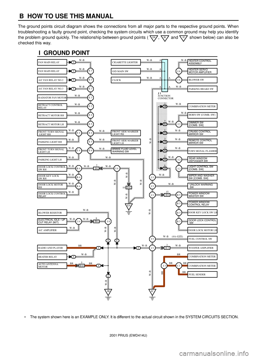
The ground points circuit diagram shows the connections from all major parts to the respective ground points. When
troubleshooting a faulty ground point, checking the system circuits which use a common ground may help you identify
the problem ground quickly. The relationship between ground points (
EA, IB and IC shown below) can also be
checked this way.
���� ���� ���� ���� ���� ���� ���� ���� ���� ���� ���� ���� ���� ���� ���� ���� ���� ���� ����
I GROUND POINT
FAN MAIN RELAY
FAN MAIN RELAY
A/C FAN RELAY NO.2
A/C FAN RELAY NO.3
RADIATOR FAN MOTOR
RETRACT CONTROL
RELAY
RETRACT MOTOR RH
RETRACT MOTOR LH
FRONT TURN SIGNAL
LIGHT RH
PARKING LIGHT RH
FRONT TURN SIGNAL
LIGHT LH
PARKING LIGHT LH
DOOR LOCK CONTROL
SW RH
DOOR KEY LOCK
SW RH
DOOR LOCK MOTOR
RH
BLOWER RESISTOR
A/C AMPLIFIER
RADIO AND PLAYER
HEATER RELAY
AUTO ANTENNA
MOTOR
BLOWER SW
PARKING BRAKE SW
COMBINATION METER
HORN SW [COMB. SW]
TURN SIGNAL FLASHER
DOOR KEY LOCK SW LH
DOOR LOCK MOTOR LH
FUEL CONTROL SW
WOOFER AMPLIFIER
COMBINATION METER
COMBINATION METER
FUEL SENDER
CIGARETTE LIGHTER
O/D MAIN SW
CLOCK
5
5
5
5
4
4
4
4
4BA15
IB18
EA2 10
3E5
3E
6 3G
13 3F
3 3D
1 3B
7
ID115
IC33
IA12
E 3
A
A AW±B
W±BW±B W±B
W±B W±B
W±B
W±B
W±B
W±B
W±B
W±B
W±B
W±B
W±B W±BW±B W±B W±B W±B
W±B W±B
W±BW±B
W±B
W±B
W±B W±B
W±B
BR
W±B
BR BRW±BW±B
W±B
W±B
W±B
W±B
W±B
W±B
W±B
W±B
W±B W±B
W±B
W±B
W±B
W±B
BR W±B
BR BR
BR W±B W±BW±B
W±BW±BBR W±B (4A±GZE)
W±B A A A
I 6
I 6
I 2
I 2
I 2
B 5I 5
I 5
I 5
B 5
B 5
B 5
I 5
I 5
I 3I 3
E 3
E 3
E 3
E 2
E 4
E 5
E 4
E 5
E 6E 4
E 4
B 4
EAI 4
B 4
B 4
I 4I 8
IBIC
3C7
4
JUNCTION
CONNECTOR J 1
4
DOOR LOCK CONTROL
RELAY
ELECTRICAL IDLE-UP
CUT RELAY (M/T)FRONT SIDE MARKER
LIGHT RH
FRONT SIDE MARKER
LIGHT LH
BRAKE FLUID LEVEL
WARNING SW
UNLOCK WARNING
SW WIPER AND WASHER
SW [COMB. SW] LIGHT CONTROL SW
[COMB. SW] HEATER CONTROL
ASSEMBLY
HEATER SERVO
MOTOR AMPLIFIER
DIMMER SW
[COMB. SW]
CRUISE CONTROL
MIRROR SW
REAR WINDOW
DEFOGGER SW
POWER WINDOW
MASTER SW
POWER WINDOW
CONTROL RELAY
DOOR LOCK CONTROL
SW
REMOTE CONTROL
MIRROR SW
*The system shown here is an EXAMPLE ONLY. It is different to the actual circuit shown in the SYSTEM CIRCUITS SECTION.
Page 510 of 1943

MA02G±02
MA±4
± MAINTENANCEUNDER HOOD
57 Author�: Date�:
2001 PRIUS (RM778U)
UNDER HOOD
GENERAL MAINTENANCE
1. GENERAL NOTES
�Maintenance items may vary from country to country. Check the owner's manual supplement in which
the maintenance schedule is shown.
�Every serice item in the periodic maintenance schedule must be performed.
�Periodic maintenance service must be performed according to whichever interval in the periodic main-
tenance schedule occurs first, the odometer reading (miles) or the time interval (months).
�Maintenance service after the last period should be performed at the same interval as before unless
otherwise noted.
2. WINDSHIELD WASHER FLUID
Check that there is sufficient fluid in the tank.
3. ENGINE COOLANT LEVEL
Check that the coolant level is between the ºFULLº and ºLOWº lines on the see±through reservoir.
4. RADIATOR AND HOSES
(a) Check that the front of the radiator is clean and not blocked with leaves, dirt or bugs.
(b) Check the hoses for cracks, kinks, rot or loose connections.
5. BRAKE FLUID LEVELS
Check that the brake fluid levels are near the upper level line on the see±through reservoirs.
6. CHECK TRANSAXLE OIL (FLUID)
�Visually check the transaxle for oil (fluid) leakage.
�If leakage is found, check for the cause and repair.
HINT:
Wait until the engine and motor cools down (approx. 30 min.) before checking the fluid level after extended
driving at high speeds, in hot weather, in heavy traffic or pulling a trailer.
Page 1689 of 1943
F09780
F12390
SST
BR±34
± BRAKEREAR DRUM BRAKE
2001 PRIUS (RM778U)
(b) Using needle±nose pliers, disconnect the parking brake
cable from the parking brake lever, and remove the rear
shoe.
6. REMOVE PARKING BRAKE LEVER
(a) Remove the C±washer.
(b) Remove the parking brake lever from the rear shoe.
7. REMOVE WHEEL CYLINDER
(a) Using SST, disconnect the brake line. Use container to
catch the brake fluid.
SST 09751±36011
Torque: 15 N´m (155 kgf´cm, 11 ft´lbf)
(b) Remove the bolt and the wheel cylinder.
Torque: 10 N´m (100 kgf´cm, 7 ft´lbf)
8. DISASSEMBLE WHEEL CYLINDER
(a) Remove the 2 boots from the wheel cylinder.
(b) Remove the 2 pistons from the wheel cylinder.
(c) Remove the spring from the wheel cylinder.
(d) Remove the 2 piston cups from each piston.
Page 1763 of 1943

BE±6
± BODY ELECTRICALTROUBLESHOOTING
1673 Author�: Date�:
2001 PRIUS (RM778U)
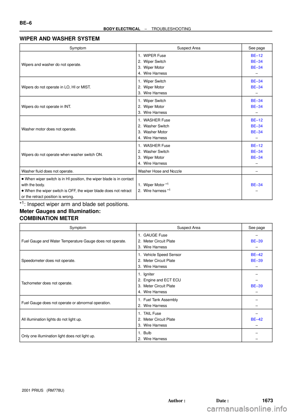
WIPER AND WASHER SYSTEM
SymptomSuspect AreaSee page
Wipers and washer do not operate.
1. WIPER Fuse
2. Wiper Switch
3. Wiper Motor
4. Wire HarnessBE±12
BE±34
BE±34
±
Wipers do not operate in LO, HI or MIST.
1. Wiper Switch
2. Wiper Motor
3. Wire HarnessBE±34
BE±34
±
Wipers do not operate in INT.
1. Wiper Switch
2. Wiper Motor
3. Wire HarnessBE±34
BE±34
±
Washer motor does not operate.
1. WASHER Fuse
2. Washer Switch
3. Washer Motor
4. Wire HarnessBE±12
BE±34
BE±34
±
Wipers do not operate when washer switch ON.
1. WASHER Fuse
2. Washer Switch
3. Wiper Motor
4. Wire HarnessBE±12
BE±34
BE±34
±
Washer fluid does not operate.Washer Hose and Nozzle±
� When wiper switch is in HI position, the wiper blade is in contact
with the body.
� When the wiper switch is OFF, the wiper blade does not retract
or the retract position is wrong.
1. Wiper Motor *1
2. Wire harness *1BE±34
±
*1: Inspect wiper arm and blade set positions.
Meter Gauges and Illumination:
COMBINATION METER
SymptomSuspect AreaSee page
Fuel Gauge and Water Temperature Gauge does not operate.
1. GAUGE Fuse
2. Meter Circuit Plate
3. Wire Harness±
BE±39
±
Speedometer does not operate.
1. Vehicle Speed Sensor
2. Meter Circuit Plate
3. Wire HarnessBE±42
BE±39
±
Tachometer does not operate.
1. Igniter
2. Engine and ECT ECU
3. Meter Circuit Plate
4. Wire Harness±
±
BE±39
±
Fuel Gauge does not operate or abnormal operation.1. Fuel Tank Assembly
2. Wire Harness±
±
All illumination lights do not light up.
1. TAIL Fuse
2. Meter Circuit Plate
3. Wire Harness±
BE±42
±
Only one illumination light does not light up.1. Bulb
2. Wire Harness±
±