Page 514 of 1943
P21235
MA049±01
F12933
F12919
MA±8
± MAINTENANCEBODY
61 Author�: Date�:
2001 PRIUS (RM778U)
BODY
INSPECTION
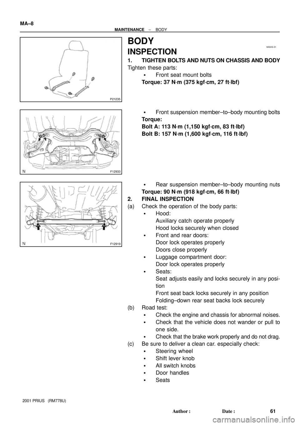
1. TIGHTEN BOLTS AND NUTS ON CHASSIS AND BODY
Tighten these parts:
�Front seat mount bolts
Torque: 37 N´m (375 kgf´cm, 27 ft´lbf)
�Front suspension member±to±body mounting bolts
Torque:
Bolt A: 113 N´m (1,150 kgf´cm, 83 ft´lbf)
Bolt B: 157 N´m (1,600 kgf´cm, 116 ft´lbf)
�Rear suspension member±to±body mounting nuts
Torque: 90 N´m (918 kgf´cm, 66 ft´lbf)
2. FINAL INSPECTION
(a) Check the operation of the body parts:
�Hood:
Auxiliary catch operate properly
Hood locks securely when closed
�Front and rear doors:
Door lock operates properly
Doors close properly
�Luggage compartment door:
Door lock operates properly
�Seats:
Seat adjusts easily and locks securely in any posi-
tion
Front seat back locks securely in any position
Folding±down rear seat backs lock securely
(b) Road test:
�Check the engine and chassis for abnormal noises.
�Check that the vehicle does not wander or pull to
one side.
�Check that the brake work properly and do not drag.
(c) Be sure to deliver a clean car. especially check:
�Steering wheel
�Shift lever knob
�All switch knobs
�Door handles
�Seats
Page 1514 of 1943
A13915
A13916
A13917
SST
SST
A13918
SST SST
EM±56
± ENGINE MECHANICALENGINE UNIT
2001 PRIUS (RM778U)
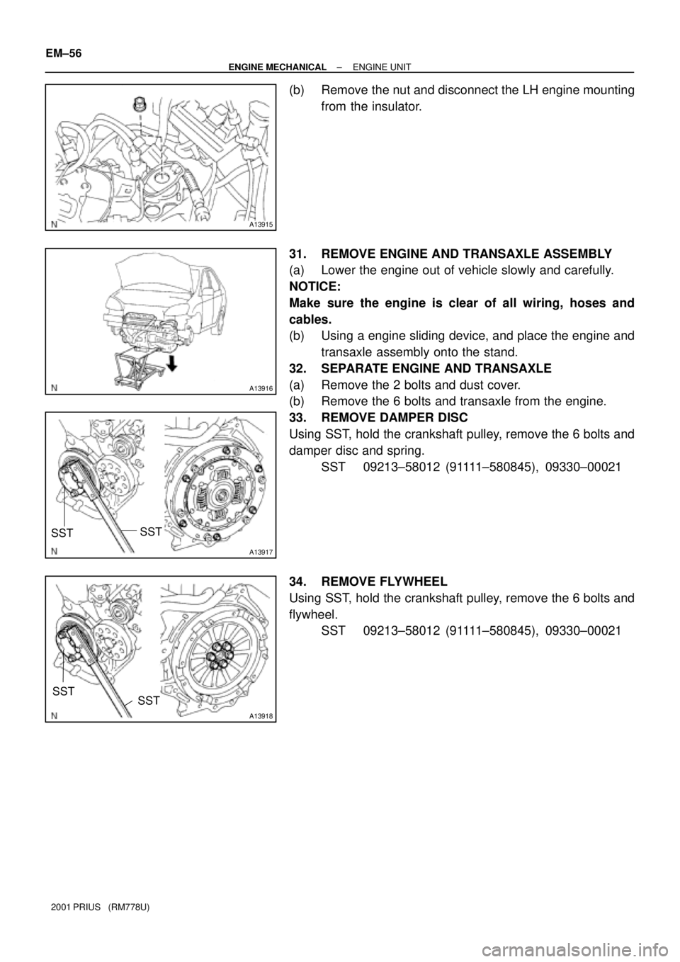
(b) Remove the nut and disconnect the LH engine mounting
from the insulator.
31. REMOVE ENGINE AND TRANSAXLE ASSEMBLY
(a) Lower the engine out of vehicle slowly and carefully.
NOTICE:
Make sure the engine is clear of all wiring, hoses and
cables.
(b) Using a engine sliding device, and place the engine and
transaxle assembly onto the stand.
32. SEPARATE ENGINE AND TRANSAXLE
(a) Remove the 2 bolts and dust cover.
(b) Remove the 6 bolts and transaxle from the engine.
33. REMOVE DAMPER DISC
Using SST, hold the crankshaft pulley, remove the 6 bolts and
damper disc and spring.
SST 09213±58012 (91111±580845), 09330±00021
34. REMOVE FLYWHEEL
Using SST, hold the crankshaft pulley, remove the 6 bolts and
flywheel.
SST 09213±58012 (91111±580845), 09330±00021
Page 1515 of 1943
EM1J2±02
P08755
A13917
SSTSST
1
2
3
4
6
5
A13940
SST
A13917
SSTSST
1
2
3
4
6
5
EM±58
± ENGINE MECHANICALENGINE UNIT
2001 PRIUS (RM778U)
INSTALLATION
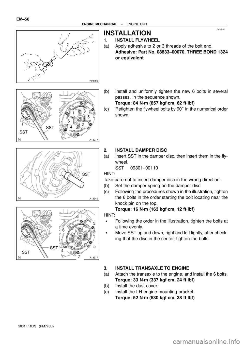
1. INSTALL FLYWHEEL
(a) Apply adhesive to 2 or 3 threads of the bolt end.
Adhesive: Part No. 08833±00070, THREE BOND 1324
or equivalent
(b) Install and uniformly tighten the new 6 bolts in several
passes, in the sequence shown.
Torque: 84 N´m (857 kgf´cm, 62 ft´lbf)
(c) Retighten the flywheel bolts by 90° in the numerical order
shown.
2. INSTALL DAMPER DISC
(a) Insert SST in the damper disc, then insert them in the fly-
wheel.
SST 09301±00110
HINT:
Take care not to insert damper disc in the wrong direction.
(b) Set the damper spring on the damper disc.
(c) Following the procedures shown in the illustration, tighten
the 6 bolts in the order starting the bolt locating near the
knock pin on the top.
Torque: 16 N´m (163 kgf´cm, 12 ft´lbf)
HINT:
�Following the order in the illustration, tighten the bolts at
a time evenly.
�Move SST up and down, right and left lightly, after check-
ing that the disc in the center, tighten the bolts.
3. INSTALL TRANSAXLE TO ENGINE
(a) Attach the transaxle to the engine, and install the 6 bolts.
Torque: 33 N´m (337 kgf´cm, 24 ft´lbf)
(b) Install the dust cover.
(c) Install the LH engine mounting bracket.
Torque: 52 N´m (530 kgf´cm, 38 ft´lbf)
Page 1656 of 1943
F11573
Front:
Rear:SA1CK±11
Z03382
Alignment
TesterGauge
F07339
SA±4
± SUSPENSION AND AXLEFRONT WHEEL ALIGNMENT
1454 Author�: Date�:
2001 PRIUS (RM778U)
FRONT WHEEL ALIGNMENT
INSPECTION
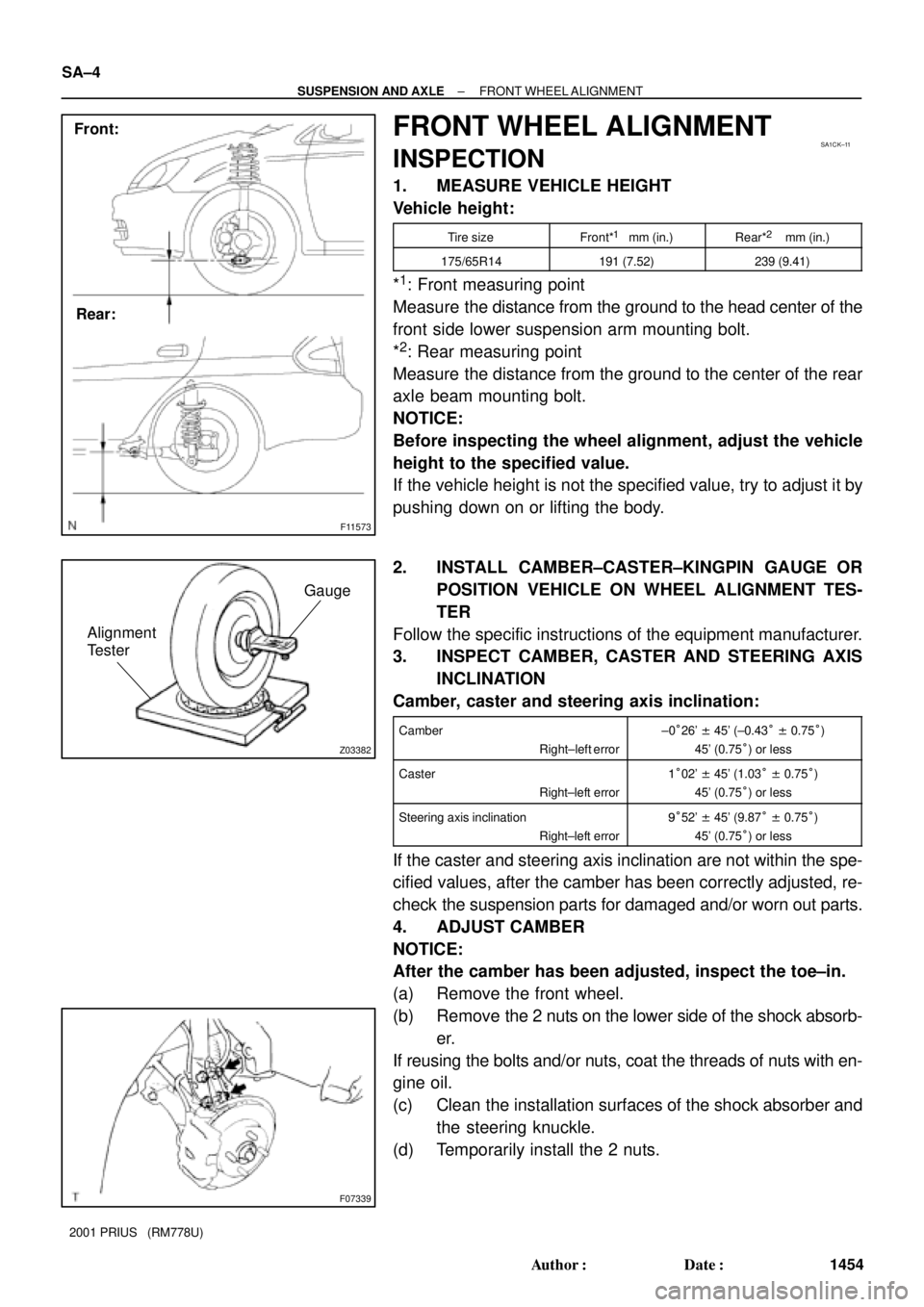
1. MEASURE VEHICLE HEIGHT
Vehicle height:
Tire sizeFront*1 mm (in.)Rear*2 mm (in.)
175/65R14191 (7.52)239 (9.41)
*1: Front measuring point
Measure the distance from the ground to the head center of the
front side lower suspension arm mounting bolt.
*
2: Rear measuring point
Measure the distance from the ground to the center of the rear
axle beam mounting bolt.
NOTICE:
Before inspecting the wheel alignment, adjust the vehicle
height to the specified value.
If the vehicle height is not the specified value, try to adjust it by
pushing down on or lifting the body.
2. INSTALL CAMBER±CASTER±KINGPIN GAUGE OR
POSITION VEHICLE ON WHEEL ALIGNMENT TES-
TER
Follow the specific instructions of the equipment manufacturer.
3. INSPECT CAMBER, CASTER AND STEERING AXIS
INCLINATION
Camber, caster and steering axis inclination:
Camber
Right±left error±0°26' ± 45' (±0.43° ± 0.75°)
45' (0.75°) or less
Caster
Right±left error1°02' ± 45' (1.03° ± 0.75°)
45' (0.75°) or less
Steering axis inclination
Right±left error9°52' ± 45' (9.87° ± 0.75°)
45' (0.75°) or less
If the caster and steering axis inclination are not within the spe-
cified values, after the camber has been correctly adjusted, re-
check the suspension parts for damaged and/or worn out parts.
4. ADJUST CAMBER
NOTICE:
After the camber has been adjusted, inspect the toe±in.
(a) Remove the front wheel.
(b) Remove the 2 nuts on the lower side of the shock absorb-
er.
If reusing the bolts and/or nuts, coat the threads of nuts with en-
gine oil.
(c) Clean the installation surfaces of the shock absorber and
the steering knuckle.
(d) Temporarily install the 2 nuts.
Page 1657 of 1943
F07326
� �
1
2
: Use with adjusting bolt
F12938
Bolt
Adjusting
ValueSet BoltAdjusting Bolt90105±15001 90105±15004 90105±15005 90105±15006
121212121 Dot
2 Dots3 Dots
±1°30' ± ±1°15'
±1°15' ± ±1°00'
±1°00' ± ±45'
±45' ± ±30'
±30' ± ±15'
0' ± 15'
15' ± 30'
30' ± 45'
45' ± 1°00'
1°00' ± 1°15' ±15' ± 0'
1°15' ± 1°30'
± SUSPENSION AND AXLEFRONT WHEEL ALIGNMENT
SA±5
1455 Author�: Date�:
2001 PRIUS (RM778U)
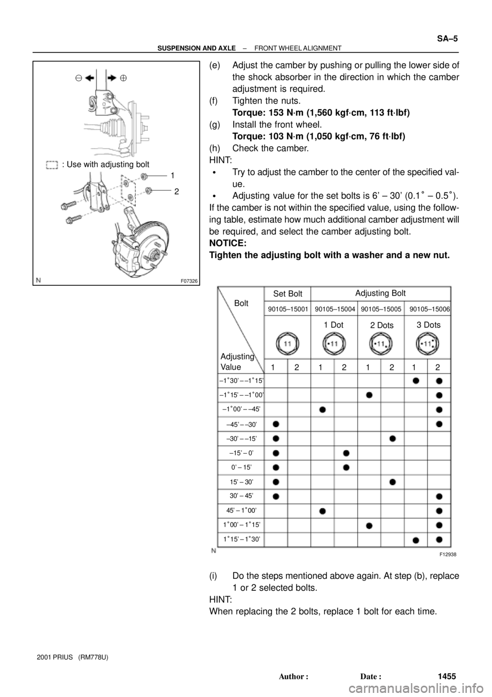
(e) Adjust the camber by pushing or pulling the lower side of
the shock absorber in the direction in which the camber
adjustment is required.
(f) Tighten the nuts.
Torque: 153 N´m (1,560 kgf´cm, 113 ft´lbf)
(g) Install the front wheel.
Torque: 103 N´m (1,050 kgf´cm, 76 ft´lbf)
(h) Check the camber.
HINT:
�Try to adjust the camber to the center of the specified val-
ue.
�Adjusting value for the set bolts is 6' ± 30' (0.1° ± 0.5°).
If the camber is not within the specified value, using the follow-
ing table, estimate how much additional camber adjustment will
be required, and select the camber adjusting bolt.
NOTICE:
Tighten the adjusting bolt with a washer and a new nut.
(i) Do the steps mentioned above again. At step (b), replace
1 or 2 selected bolts.
HINT:
When replacing the 2 bolts, replace 1 bolt for each time.
Page 1659 of 1943
SA1ZR±01
F08617
R14731
Backlash:Deviation:
F12940SST
± SUSPENSION AND AXLEFRONT AXLE HUB
SA±9
2001 PRIUS (RM778U)
REMOVAL
1. REMOVE FRONT WHEEL
Torque: 103 N´m (1,050 kgf´cm, 76 ft´lbf)
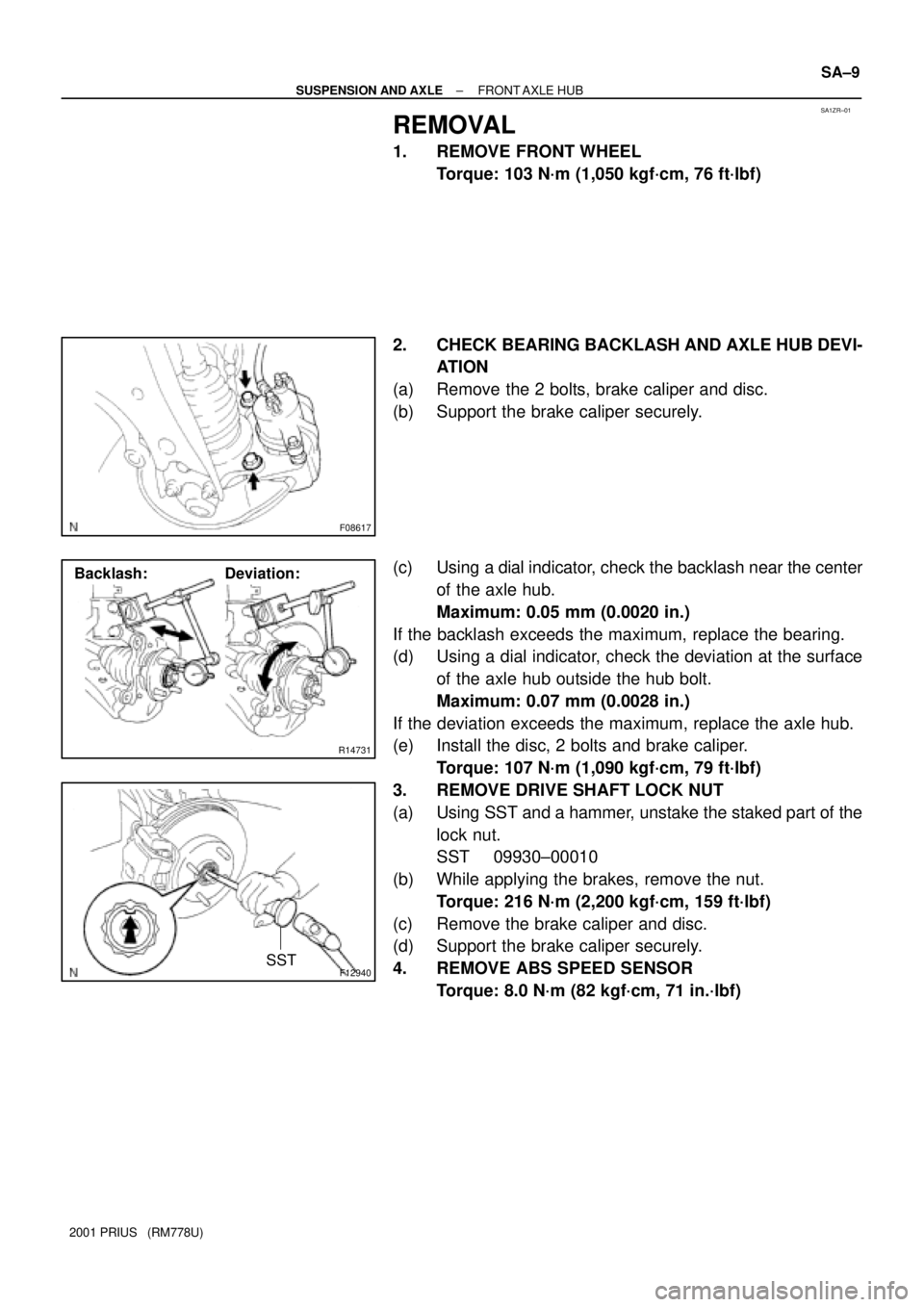
2. CHECK BEARING BACKLASH AND AXLE HUB DEVI-
ATION
(a) Remove the 2 bolts, brake caliper and disc.
(b) Support the brake caliper securely.
(c) Using a dial indicator, check the backlash near the center
of the axle hub.
Maximum: 0.05 mm (0.0020 in.)
If the backlash exceeds the maximum, replace the bearing.
(d) Using a dial indicator, check the deviation at the surface
of the axle hub outside the hub bolt.
Maximum: 0.07 mm (0.0028 in.)
If the deviation exceeds the maximum, replace the axle hub.
(e) Install the disc, 2 bolts and brake caliper.
Torque: 107 N´m (1,090 kgf´cm, 79 ft´lbf)
3. REMOVE DRIVE SHAFT LOCK NUT
(a) Using SST and a hammer, unstake the staked part of the
lock nut.
SST 09930±00010
(b) While applying the brakes, remove the nut.
Torque: 216 N´m (2,200 kgf´cm, 159 ft´lbf)
(c) Remove the brake caliper and disc.
(d) Support the brake caliper securely.
4. REMOVE ABS SPEED SENSOR
Torque: 8.0 N´m (82 kgf´cm, 71 in.´lbf)
Page 1671 of 1943
SA1ZW±01
F11576
SST
F11616
F11617
F11586
± SUSPENSION AND AXLEFRONT LOWER SUSPENSION ARM
SA±33
2001 PRIUS (RM778U)
REMOVAL
1. REMOVE FRONT WHEEL
Torque: 103 N´m (1,050 kgf´cm, 76 ft´lbf)
2. REMOVE ENGINE UNDER COVER
3. REMOVE LOWER SUSPENSION ARM
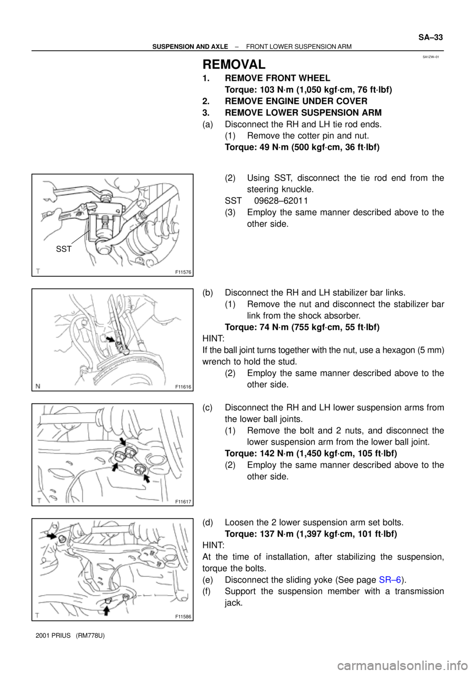
(a) Disconnect the RH and LH tie rod ends.
(1) Remove the cotter pin and nut.
Torque: 49 N´m (500 kgf´cm, 36 ft´lbf)
(2) Using SST, disconnect the tie rod end from the
steering knuckle.
SST 09628±62011
(3) Employ the same manner described above to the
other side.
(b) Disconnect the RH and LH stabilizer bar links.
(1) Remove the nut and disconnect the stabilizer bar
link from the shock absorber.
Torque: 74 N´m (755 kgf´cm, 55 ft´lbf)
HINT:
If the ball joint turns together with the nut, use a hexagon (5 mm)
wrench to hold the stud.
(2) Employ the same manner described above to the
other side.
(c) Disconnect the RH and LH lower suspension arms from
the lower ball joints.
(1) Remove the bolt and 2 nuts, and disconnect the
lower suspension arm from the lower ball joint.
Torque: 142 N´m (1,450 kgf´cm, 105 ft´lbf)
(2) Employ the same manner described above to the
other side.
(d) Loosen the 2 lower suspension arm set bolts.
Torque: 137 N´m (1,397 kgf´cm, 101 ft´lbf)
HINT:
At the time of installation, after stabilizing the suspension,
torque the bolts.
(e) Disconnect the sliding yoke (See page SR±6).
(f) Support the suspension member with a transmission
jack.
Page 1687 of 1943
F12060
± BRAKEFRONT BRAKE PAD
BR±25
2001 PRIUS (RM778U)
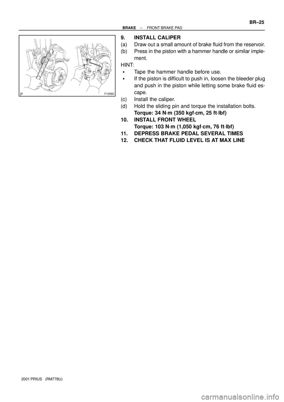
9. INSTALL CALIPER
(a) Draw out a small amount of brake fluid from the reservoir.
(b) Press in the piston with a hammer handle or similar imple-
ment.
HINT:
�Tape the hammer handle before use.
�If the piston is difficult to push in, loosen the bleeder plug
and push in the piston while letting some brake fluid es-
cape.
(c) Install the caliper.
(d) Hold the sliding pin and torque the installation bolts.
Torque: 34 N´m (350 kgf´cm, 25 ft´lbf)
10. INSTALL FRONT WHEEL
Torque: 103 N´m (1,050 kgf´cm, 76 ft´lbf)
11. DEPRESS BRAKE PEDAL SEVERAL TIMES
12. CHECK THAT FLUID LEVEL IS AT MAX LINE