2001 TOYOTA PRIUS fuel
[x] Cancel search: fuelPage 8 of 1943
2001 PRIUS (EWD414U)
B HOW TO USE THIS MANUAL
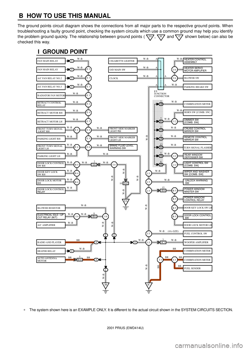
The ground points circuit diagram shows the connections from all major parts to the respective ground points. When
troubleshooting a faulty ground point, checking the system circuits which use a common ground may help you identify
the problem ground quickly. The relationship between ground points (
EA, IB and IC shown below) can also be
checked this way.
I GROUND POINT
FAN MAIN RELAY
FAN MAIN RELAY
A/C FAN RELAY NO.2
A/C FAN RELAY NO.3
RADIATOR FAN MOTOR
RETRACT CONTROL
RELAY
RETRACT MOTOR RH
RETRACT MOTOR LH
FRONT TURN SIGNAL
LIGHT RH
PARKING LIGHT RH
FRONT TURN SIGNAL
LIGHT LH
PARKING LIGHT LH
DOOR LOCK CONTROL
SW RH
DOOR KEY LOCK
SW RH
DOOR LOCK MOTOR
RH
BLOWER RESISTOR
A/C AMPLIFIER
RADIO AND PLAYER
HEATER RELAY
AUTO ANTENNA
MOTOR
BLOWER SW
PARKING BRAKE SW
COMBINATION METER
HORN SW [COMB. SW]
TURN SIGNAL FLASHER
DOOR KEY LOCK SW LH
DOOR LOCK MOTOR LH
FUEL CONTROL SW
WOOFER AMPLIFIER
COMBINATION METER
COMBINATION METER
FUEL SENDER
CIGARETTE LIGHTER
O/D MAIN SW
CLOCK
5
5
5
5
4
4
4
4
4BA15
IB18
EA2 10
3E5
3E
6 3G
13 3F
3 3D
1 3B
7
ID115
IC33
IA12
E 3
A
A AW±B
W±BW±B W±B
W±B W±B
W±B
W±B
W±B
W±B
W±B
W±B
W±B
W±B
W±B W±BW±B W±B W±B W±B
W±B W±B
W±BW±B
W±B
W±B
W±B W±B
W±B
BR
W±B
BR BRW±BW±B
W±B
W±B
W±B
W±B
W±B
W±B
W±B
W±B
W±B W±B
W±B
W±B
W±B
W±B
BR W±B
BR BR
BR W±B W±BW±B
W±BW±BBR W±B (4A±GZE)
W±B A A A
I 6
I 6
I 2
I 2
I 2
B 5I 5
I 5
I 5
B 5
B 5
B 5
I 5
I 5
I 3I 3
E 3
E 3
E 3
E 2
E 4
E 5
E 4
E 5
E 6E 4
E 4
B 4
EAI 4
B 4
B 4
I 4I 8
IBIC
3C7
4
JUNCTION
CONNECTOR J 1
4
DOOR LOCK CONTROL
RELAY
ELECTRICAL IDLE-UP
CUT RELAY (M/T)FRONT SIDE MARKER
LIGHT RH
FRONT SIDE MARKER
LIGHT LH
BRAKE FLUID LEVEL
WARNING SW
UNLOCK WARNING
SW WIPER AND WASHER
SW [COMB. SW] LIGHT CONTROL SW
[COMB. SW] HEATER CONTROL
ASSEMBLY
HEATER SERVO
MOTOR AMPLIFIER
DIMMER SW
[COMB. SW]
CRUISE CONTROL
MIRROR SW
REAR WINDOW
DEFOGGER SW
POWER WINDOW
MASTER SW
POWER WINDOW
CONTROL RELAY
DOOR LOCK CONTROL
SW
REMOTE CONTROL
MIRROR SW
*The system shown here is an EXAMPLE ONLY. It is different to the actual circuit shown in the SYSTEM CIRCUITS SECTION.
Page 17 of 1943

*The titles given inside the components are the names of the terminals (terminal codes) and are not treated as being
abbreviations.
2001 PRIUS (EWD414U)
ABBREVIATIONS D
ABBREVIATIONS
The following abbreviations are used in this manual.
ABS = Anti±Lock Brake System
A/C = Air Conditioning
COMB. = Combination
DC = Direct Current
ECU = Electronic Control Unit
EMPS = Electric Motor Power Steering
ESA = Electronic Spark Advance
EVAP = Evaporative Emission
HV = Hybrid Vehicle
J/B = Junction Block
LH = Left±Hand
PTC = Positive Temperature Coefficient
R/B = Relay Block
RH = Right±Hand
SFI = Sequential Multiport Fuel Injection
SRS = Supplemental Restraint System
SW = Switch
TEMP. = Temperature
VSV = Vacuum Switching Valve
w/ = With
w/o = Without
Page 18 of 1943
2001 PRIUS (EWD414U)
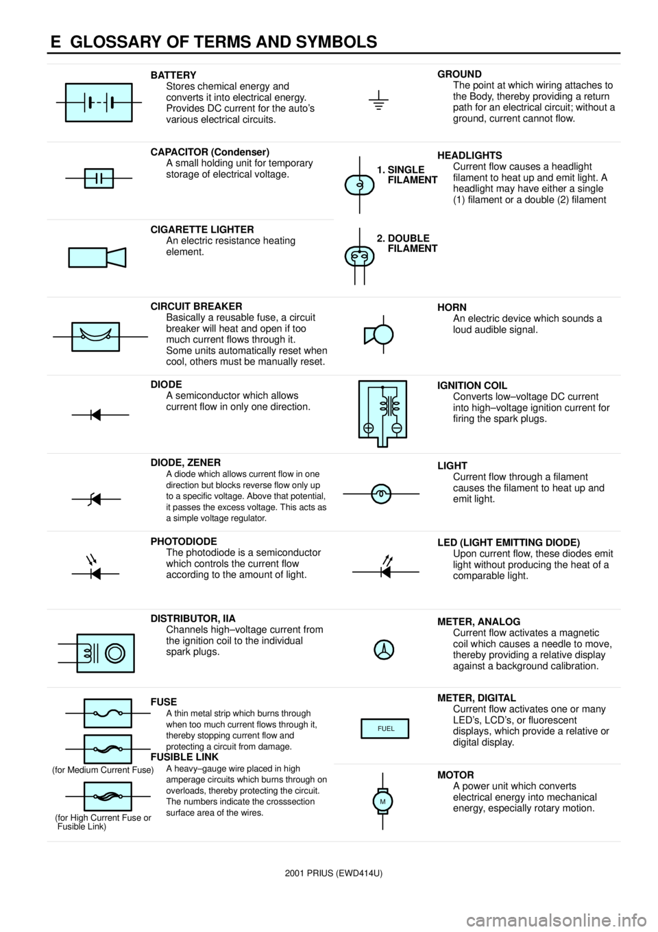
E GLOSSARY OF TERMS AND SYMBOLS
BATTERY
Stores chemical energy and
converts it into electrical energy.
Provides DC current for the auto's
various electrical circuits.GROUND
The point at which wiring attaches to
the Body, thereby providing a return
path for an electrical circuit; without a
ground, current cannot flow.
CAPACITOR (Condenser)
A small holding unit for temporary
storage of electrical voltage.HEADLIGHTS
Current flow causes a headlight
filament to heat up and emit light. A
headlight may have either a single
(1) filament or a double (2) filament
1. SINGLE
FILAMENT
CIGARETTE LIGHTER
An electric resistance heating
element.2. DOUBLE
FILAMENT
CIRCUIT BREAKER
Basically a reusable fuse, a circuit
breaker will heat and open if too
much current flows through it.
Some units automatically reset when
cool, others must be manually reset.HORN
An electric device which sounds a
loud audible signal.
DIODE
A semiconductor which allows
current flow in only one direction.IGNITION COIL
Converts low±voltage DC current
into high±voltage ignition current for
firing the spark plugs.
DIODE, ZENERA diode which allows current flow in one
direction but blocks reverse flow only up
to a specific voltage. Above that potential,
it passes the excess voltage. This acts as
a simple voltage regulator.LIGHT
Current flow through a filament
causes the filament to heat up and
emit light.
PHOTODIODE
The photodiode is a semiconductor
which controls the current flow
according to the amount of light.LED (LIGHT EMITTING DIODE)
Upon current flow, these diodes emit
light without producing the heat of a
comparable light.
DISTRIBUTOR, IIA
Channels high±voltage current from
the ignition coil to the individual
spark plugs.METER, ANALOG
Current flow activates a magnetic
coil which causes a needle to move,
thereby providing a relative display
against a background calibration.
FUSEA thin metal strip which burns through
when too much current flows through it,
thereby stopping current flow and
protecting a circuit from damage.
FUSIBLE LINK
METER, DIGITAL
Current flow activates one or many
LED's, LCD's, or fluorescent
displays, which provide a relative or
digital display.
FUEL
FUSIBLE LINK
A heavy±gauge wire placed in high
amperage circuits which burns through on
overloads, thereby protecting the circuit.
The numbers indicate the crosssection
surface area of the wires.(for Medium Current Fuse)
(for High Current Fuse or
Fusible Link)MOTOR
A power unit which converts
electrical energy into mechanical
energy, especially rotary motion.
M
Page 38 of 1943

2001 PRIUS (EWD414U)
G ELECTRICAL WIRING ROUTING
Position of Parts in Body
A 23 ABS Speed Sensor Rear LH
A 24 ABS Speed Sensor Rear RH
B 15 Battery Blower Motor
B 16 Battery Blower Motor Controller
B 17 Battery ECU
B 18 Battery ECU
B 19 Battery Fan Relay
B 20 Buckle SW and Tension Reducer LH
B 21 Buckle SW RH and
Seat Belt Warning Occupant Detection Sensor
D 6 Door Courtesy SW Front LH
D 7 Door Courtesy SW Front RH
D 8 Door Courtesy SW Rear LH
D 9 Door Courtesy SW Rear RH
D 10 Door Lock Control SW Front RH
D 11 Door Lock Motor and Door Unlock Detection SW
Rear LH
D 12 Door Lock Motor and Door Unlock Detection SW
Rear RH
D 13 Door Lock Motor, Door Key Lock and Unlock SW and
Door Unlock Detection SW Front LH
D 14 Door Lock Motor, Door Key Lock and Unlock SW and
Door Unlock Detection SW Front RHF 14 Front Door Speaker LH
F 15 Front Door Speaker RH
F 16 Fuel Pump and Fuel Sender
F 17 Fusible Link Block No.2
F 18 Fusible Link Block No.2
H 15 High Mounted Stop Light
H 16 Hybrid Vehicle Battery
H 17 Hybrid Vehicle Battery
I 16 Interior Light
I 17 Interlock SW
J 30 Junction Connector
J 31 Junction Connector
J 32 Junction Connector
J 33 Junction Connector
L 2 License Plate Light LH
L 3 License Plate Light RH
L 4 Luggage Compartment Door Unlock SW
L 5 Luggage Compartment Light
L 6 Luggage Compartment Light SW
Page 47 of 1943

2001 PRIUS (EWD414U)
G
Connector Joining Wire Harness and Wire Harness
12345
67891054321
10987612345
67891054321
109876
1234
56781 2 3 4
5 6 7 8
BA1
GRAY
BB1
BC1
CodeJoining Wire Harness and Wire Harness (Connector Location)
BA1Rear Door No.2 Wire and Floor Wire (Center Pillar LH)
BB1Rear Door No.1 Wire and Cowl Wire (Center Pillar RH)
BC1Cowl Wire and Fuel Tank Wire (Near the Fuel Tank)
Page 66 of 1943
2001 PRIUS (EWD414U)
ENGINE CONTROL
120A MAIN
1C 1
D 11B 215A
AM2 1J 92C 2
2G 176AM2 IG2
ST2
32 512B 5
2G 11
1J 3
1K 3
BL 1A 2
EA 15A
EFI
32 51
1F 11A10 1A31A4 13 25
1F 12 1F13
IA2 4IA114
7 3
IGA C
B AIA1 19 A
AA A
FUSIBLE LINK
BLOCK NO. 2 F18
JUNCTION CONNECTORB J 4 A , J 5FUSIBLE LINK
BLOCK NO. 1D F1 2 C , F13
W±BW±B W±B W±BB±G B W±R W±R
B±W B±W
B±W
B B G±RB±R G±R
B±R
B B
BB
W±B
B
B±W
B±W
R±W
G± R
G± R
B
B B±W
B±W
A C
FUEL PUMP F1 6
CIR OPN
RELAY
EFI
RELAY FROM POWER SOURCE SYSTEM (
SEE PAGE 50)
IGNITION SW I15
IG2
RELAY
JUNCTION
CONNECTOR J17B
BATTERY
JUNCTION
CONNECTOR J 7
JUNCTION
CONNECTOR J 1
A
A
JUNCTION
CONNECTOR
IEBC1 8
A
W±BJ18
W±B W±B
M
Page 72 of 1943

2001 PRIUS (EWD414U)
ENGINE CONTROL
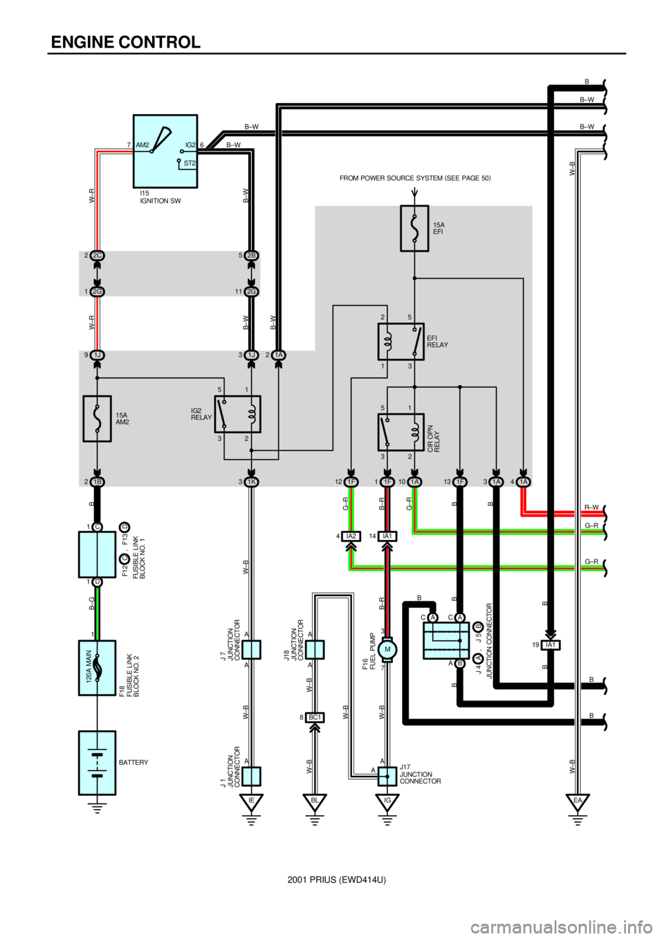
This system utilizes an engine control module and maintains overall control of the engine, transmission and so on. An outline
of the engine control is explained here.
1. INPUT SIGNALS
(1) Engine coolant temp. signal circuit
The engine coolant temp. sensor detects the engine coolant temp. and has a built±in thermistor with a resistance which
varies according to the engine coolant temp. thus the engine coolant temp. is input in the form of a control signal into
TERMINAL THW of the engine control module.
(2) Intake air temp. signal circuit
The intake air temp. sensor is installed in the mass air flow meter and detects the intake air temp., which is input as a
control signal into TERMINAL THA of the engine control module.
(3) Oxygen sensor signal circuit
The oxygen density in the exhaust gases is detected and input as a control signal into TERMINALS OX1A and OX1B of
the engine control module.
(4) RPM signal circuit
Camshaft position and crankshaft position are detected by the camshaft position sensor and crankshaft position sensor.
Camshaft position is input as a control signal to TERMINAL G2 of the engine control module, and engine RPM is input
into TERMINAL NE+.
(5) Throttle signal circuit
The throttle position sensor detects the throttle valve opening angle, which is input as a control signal into TERMINALS
VTA and VTA2 of the engine control module.
(6) Vehicle speed signal circuit
The vehicle speed signal from brake ECU, detects the vehicle speed and inputs a control signal into TERMINAL SPD of
the engine control module via the combination meter.
(7) Battery signal circuit
Voltage is constantly applied to TERMINAL BATT of the engine control module. When the ignition SW is turned on, the
voltage for engine control module start±up power supply is applied to TERMINAL +B of the engine control module via
EFI relay.
(8) Engine knock signal circuit
Engine knocking is detected by knock sensor and the signal is input into TERMINAL KNK1 of the engine control module
as a control signal.
2. CONTROL SYSTEM
*SFI system
The SFI system monitors the engine condition through the signals, which are input from each sensor to the engine
control module. The best fuel injection volume is decided based on this data and the program memorized by the engine
control module, and the control signal is output to TERMINALS #10, #20, #30 and #40 of the engine control module to
operate the injector. (Inject the fuel). The SFI system produces control of fuel injection operation by the engine control
module in response to the driving conditions.
*ESA system
The ESA system monitors the engine condition through the signals, which are input to the engine control module from
each sensor. The best ignition timing is detected according to this data and the memorized data in the engine control
module, and the control signal is output to TERMINALS IGT1, IGT2, IGT3 and IGT4. This signal controls the ignition coil
and igniter to provide the best ignition timing for the driving conditions.
*Fuel pump control system
The engine control module operation outputs to TERMINAL FC and controls the CIR OPN relay. Thus controls the fuel
pump drive speed in response to conditions.
3. DIAGNOSIS SYSTEM
With the diagnosis system, when there is a malfunctioning in the engine control module signal system, the malfunction
system is recorded in the memory. The malfunctioning system can then be found by reading the display (Code) of the
malfunction indicator lamp.
4. FAIL±SAFE SYSTEM
When a malfunction occurs in any system, if there is a possibility of engine trouble being caused by continued control based
on the signals from that system, the fail±safe system either controls the system by using data (Standard values) recorded in
the engine control module memory or else stops the engine.
SYSTEM OUTLINE
Page 74 of 1943
2001 PRIUS (EWD414U)
ENGINE CONTROL
: JUNCTION BLOCK AND WIRE HARNESS CONNECTOR
CodeSee PageJunction Block and Wire Harness (Connector Location)
1A27Engine Wire and Engine Room J/B (Engine Compartment Left)
1B
1F27Engine Room Main Wire and Engine Room J/B (Engine Compartment Left)1J27Engine Room Main Wire and Engine Room J/B (Engine Compartment Left)
1K
2A
2B30Instrument Panel Wire and Instrument Panel J/B (Cowl Side Panel LH)2C30Instrument Panel Wire and Instrument Panel J/B (Cowl Side Panel LH)
2D
2G31Engine Room Main Wire and Instrument Panel J/B (Cowl Side Panel LH)
2K31Cowl Wire and Instrument Panel J/B (Cowl Side Panel LH)
: CONNECTOR JOINING WIRE HARNESS AND WIRE HARNESS
CodeSee PageJoining Wire Harness and Wire Harness (Connector Location)
EA140Engine Wire and Engine No.4 Wire (Near the Radiator Fan)
IA142Engine Room Main Wire and Cowl Wire (Cowl Side Panel LH)IA242Engine Room Main Wire and Cowl Wire (Cowl Side Panel LH)
ID142Instrument Panel Wire and Cowl Wire (Left Kick Panel)ID242Instrument Panel Wire and Cowl Wire (Left Kick Panel)
IE142Instrument Panel Wire and Engine Room Main Wire (Left Kick Panel)
IK144Engine Wire and Engine Room Main Wire (Right Kick Panel)
IO144Engine Wire and Cowl Wire (Right Kick Panel)
BC146Cowl Wire and Fuel Tank Wire (Near the Fuel Tank)
: GROUND POINTS
CodeSee PageGround Points Location
EA40Engine BlockEB40Engine Block
ID42Cowl Side Panel LHIE42Cowl Side Panel LH
IG42Cowl Side Panel RH
IH42Right Kick Panel
BL46Near the Fuel Tank
: SPLICE POINTS
CodeSee PageWire Harness with Splice PointsCodeSee PageWire Harness with Splice Points
E340Engine WireI644Instrument Panel Wire
E440Engine WireI744Engine Wire