Page 356 of 1943
CHASSIS ± SUSPENSION AND AXLES
181CH24 181CH23
StraightlineNegative
Camber
Cornering
182CH31
Bound StopperRebound Stopper
Upper
Insulator
Stopper
Clearance
94
Negative Camber
The front suspension adopts negative camber to reduce the ground contact camber angle of the outer wheel
at the time of turning (cornering), which is caused when the vehicle posture changes during cornering, thus
realizing excellent cornering performance.
Suspension Upper Support and Dust Cover
�The upper support optimizes the characteris-
tics of the rubber mount. Also, a rebound stop-
per has been provided to ensure riding com-
fort, drivability, and stability.
�A bound stopper made of urethane has been
adopted. By optimizing the stopper character-
istics and the clearance, excellent riding com-
fort and a high level of roll rigidity have been
achieved.
�An upper insulator that is integrated with the
dust boot has been adopted.
Page 454 of 1943

IN00U±36
N17080
Filler Cap
Float
Reservoir
� Grommet
Clip
Slotted Spring Pin
: Specified torque
� Non±reusable partCylinder
Piston
Push Rod
Washer
Snap Ring
Boot
� Gasket
Lock Nut
Clevis Pin
Clevis
N´m (kgf´cm, ft´lbf)
12 (120, 9)
15 (155, 11)
± INTRODUCTIONHOW TO USE THIS MANUAL
IN±1
1 Author�: Date�:
2001 PRIUS (RM778U)
HOW TO USE THIS MANUAL
GENERAL INFORMATION
1. INDEX
An INDEX is provided on the first page of each section to guide you to the item to be repaired. To assist you
in finding your way through the manual, the section title and major heading are given at the top of every page.
2. PRECAUTION
At the beginning of each section, a PRECAUTION is given that pertains to all repair operations contained
in that section.
Read these precautions before starting any repair task.
3. TROUBLESHOOTING
TROUBLESHOOTING tables are included for each system to help you diagnose the problem and find the
cause. The fundamentals of how to proceed with troubleshooting are described on page IN±30.
Be sure to read this before performing troubleshooting.
4. PREPARATION
Preparation lists the SST (Special Service Tools), recommended tools, equipment, lubricant and SSM (Spe-
cial Service Materials) which should be prepared before beginning the operation and explains the purpose
of each one.
5. REPAIR PROCEDURES
Most repair operations begin with an overview illustration. It identifies the components and shows how the
parts fit together.
Example:
Page 513 of 1943

CHASSIS
INSPECTION
1. INSPECT STEERING LINKAGE
(a) Check the steering wheel freeplay. (See page SR±3)")
MA048±01
S01303
Dust Cover
± MAINTENANCECHASSIS
MA±7
60 Author�: Date�:
2001 PRIUS (RM778U)
CHASSIS
INSPECTION
1. INSPECT STEERING LINKAGE
(a) Check the steering wheel freeplay. (See page SR±3)
(b) Check the steering linkage for looseness or damage.
Check that:
�Tie rod ends do not have excessive play.
�Dust seals and boots are not damaged.
�Boot clamps are not loose.
2. INSPECT SRS AIRBAG (See page RS±2)
3. INSPECT STEERING GEAR HOUSING OIL
Check the steering gear housing for oil leakage.
4. INSPECT DRIVE SHAFT BOOTS
Check the drive shaft boots for clamp looseness, leakage or
damage.
5. INSPECT BALL JOINTS AND DUST COVERS
(a) Inspect the ball joints for excessive looseness.
�Jack up the front of the vehicle and place wooden
blocks with a height of 180 ± 200 mm (7.09 ± 7.87
in.) under the front tires.
�Lower the jack until there is about half a load on the
front coil spring. Place stands under the vehicle for
safety.
�Check that the front wheels are pointing straight
ahead, and block them with chocks.
�Using a lever, pry up the end of the lower arm, and
check the amount of play.
Maximum ball joint vertical play: 0 mm (0 in.)
If there is play, replace the ball joint.
(b) Check the dust cover for damage.
6. CHECK TRANSAXLE OIL (FLUID)
Visually check the transaxle for oil (fluid) leakage.
If leakage is found, check for the cause and repair.
7. REPLACE TRANSAXLE OIL (FLUID)
Replace the transaxle oil (See page HT±26).
Page 544 of 1943
PP3A9±01
PP±30
± PREPARATIONSUSPENSION AND AXLE
91 Author�: Date�:
2001 PRIUS (RM778U)
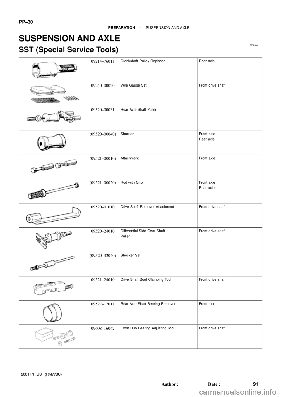
SUSPENSION AND AXLE
SST (Special Service Tools)
09214±76011Crankshaft Pulley ReplacerRear axle
09240±00020Wire Gauge SetFront drive shaft
09520±00031Rear Axle Shaft Puller
(09520±00040)ShockerFront axle
Rear axle
(09521±00010)AttachmentFront axle
(09521±00020)Rod with GripFront axle
Rear axle
09520±01010Drive Shaft Remover AttachmentFront drive shaft
09520±24010Differential Side Gear Shaft
PullerFront drive shaft
(09520±32040)Shocker Set
09521±24010Drive Shaft Boot Clamping ToolFront drive shaft
09527±17011Rear Axle Shaft Bearing RemoverFront axle
09608±16042Front Hub Bearing Adjusting ToolFront drive shaft
Page 1658 of 1943

5. INSPECT TOE±IN
Toe±in:
Toe�")
SA3213
Front A
DB
C
F11574
F11575
SA0028
Front AB
A B
A: Inside
B: Outside SA±6
± SUSPENSION AND AXLEFRONT WHEEL ALIGNMENT
1456 Author�: Date�:
2001 PRIUS (RM778U)
5. INSPECT TOE±IN
Toe±in:
Toe±in
(total)A + B: 0°06' ± 12' (0.1° ± 0.2°)
C ± D: 1 ± 2 mm (0.04 ± 0.08 in.)
If the toe±in is not within the specified value, adjust it at the rack
ends.
6. ADJUST TOE±IN
(a) Remove the rack boot set clips.
(b) Loosen the tie rod end lock nuts.
(c) Turn the right and left rack ends by an equal amount to
adjust the toe±in.
HINT:
Try to adjust the toe±in to the center of the specified value.
(d) Make sure that the lengths of the right and left rack ends
are the same.
Rack end length difference: 1.5 mm (0.059 in.) or less
(e) Torque the tie rod end lock nuts.
Torque: 74 N´m (750 kgf´cm, 55 ft´lbf)
(f) Place the boots on the seats and install the clips.
HINT:
Make sure that the boots are not twisted.
7. INSPECT WHEEL ANGLE
Turn the steering wheel fully and measure the turning angle.
Wheel turning angle:
Inside wheel42°42' ± 2°
(42.70° ± 2°)
Outside wheel: Reference35°54' (35.90°)
If the right and left inside wheel angles differ from the specified
value, check the right and left rack end lengths.
Page 1660 of 1943

5. LOOSEN 2 NUTS ON LOWER SIDE OF SHOCK AB-
SORBER
Torque: 153 N´m (1,560 kgf´cm, 113 ft´lbf)
HINT")
F12941
F11576
SST
F11617
F12941
SA±10
± SUSPENSION AND AXLEFRONT AXLE HUB
2001 PRIUS (RM778U)
5. LOOSEN 2 NUTS ON LOWER SIDE OF SHOCK AB-
SORBER
Torque: 153 N´m (1,560 kgf´cm, 113 ft´lbf)
HINT:
Do not remove the 2 bolts and nuts.
6. DISCONNECT TIE ROD END FROM STEERING
KNUCKLE
(a) Remove the cotter pin and nut.
Torque: 49 N´m (500 kgf´cm, 36 ft´lbf)
HINT:
At the time of installation, if the holes for a new cotter pin are not
aligned, tighten the nut further up to 60°.
(b) Using SST, disconnect the tie rod end from the steering
knuckle.
SST 09628±62011
7. DISCONNECT LOWER SUSPENSION ARM FROM
LOWER BALL JOINT
Remove the 2 nuts and bolt.
Torque: 142 N´m (1,450 kgf´cm, 105 ft´lbf)
8. REMOVE STEERING KNUCKLE WITH AXLE HUB
(a) Remove the 2 bolts and nuts on the lower side of the
shock absorber.
HINT:
At the time of installation, coat the nut's thread with engine oil.
(b) Remove the steering knuckle with the axle hub.
NOTICE:
Be careful not to damage the boot and ABS speed sensor
rotor.
Page 1664 of 1943

6. DISCONNECT LOWER BALL JOINT FROM LOWER
SUSPENSION ARM
Remove the 2 nuts and bolt.
Torque: 142 N´m (1,4")
F11617
F13342
F11614SST
SA±18
± SUSPENSION AND AXLEFRONT DRIVE SHAFT
2001 PRIUS (RM778U)
6. DISCONNECT LOWER BALL JOINT FROM LOWER
SUSPENSION ARM
Remove the 2 nuts and bolt.
Torque: 142 N´m (1,450 kgf´cm, 105 ft´lbf)
7. DISCONNECT DRIVE SHAFT FROM AXLE HUB
Using a plastic hammer, disconnect the drive shaft from the axle
hub.
NOTICE:
Be careful not to damage the boot and ABS speed sensor
rotor.
8. REMOVE DRIVE SHAFT
(a) Using SST, remove the drive shaft.
SST 09520±01010, 09520±24010 (09520±32040)
NOTICE:
Be careful not to damage the oil seal and dust cover.
HINT:
At the time of installation, please refer to the following items.
�Apply gear oil to the inboard joint shaft and differential
case sliding surfaces.
�Before installing the drive shaft, set the snap ring with its
opening side facing downward.
�Whether inboard joint shaft is in contact with pinion shaft
or not can be known from the sound or feeling.
�After installation, check that there is 2 ± 3 mm (0.08 ± 0.12
in.) of play in the axial direction.
�After installation, check that the drive shaft cannot be re-
moved by hand.
(b) Using a screwdriver, remove the snap ring from the in-
board joint shaft.
Page 1665 of 1943

DISASSEMBLY
1. CHECK DRIVE SHAFT
(a) Check to see that")
SA20C±01
N00191
F12937
Type A:
Type B:
R11817
Matchmarks
N00194
Matchmarks
± SUSPENSION AND AXLEFRONT DRIVE SHAFT
SA±19
2001 PRIUS (RM778U)
DISASSEMBLY
1. CHECK DRIVE SHAFT
(a) Check to see that there is no remarkable play in the out-
board joint.
(b) Check to see that the inboard joint slides smoothly in the
thrust direction.
(c) Check to see that there is no remarkable play in the radial
direction of the inboard joint.
(d) Check the boots for damage.
(e) Check the shape of the boot clamp.
2. REMOVE INBOARD JOINT SHAFT
(a) Using a screwdriver, disclamp the 2 inboard joint boot
clamps.
(b) Slide the inboard joint boot toward the outboard joint.
(c) Place matchmarks on the inboard joint shaft and tripod.
NOTICE:
Do not punch the marks.
(d) Remove the inboard joint shaft from the outboard joint
shaft.
3. REMOVE TRIPOD
(a) Using a snap ring expander, remove the snap ring.
(b) Place matchmarks on the outboard joint shaft and tripod.
NOTICE:
Do not punch the marks.
(c) Using a brass bar and hammer, tap out the tripod from the
outboard joint shaft.
NOTICE:
Do not tap the roller.
4. REMOVE INBOARD JOINT BOOT AND 2 CLAMPS
5. RH drive shaft:
REMOVE DYNAMIC DAMPER
(a) Type A clamp:
Using a screwdriver, disclamp the dynamic damper clamp
and remove it.