2001 TOYOTA PRIUS ignition system
[x] Cancel search: ignition systemPage 6 of 1943
![TOYOTA PRIUS 2001 Service Repair Manual [O]
[P]
[Q]
[R]
[S]
[T]
[U]
[V]
2001 PRIUS (EWD414U)
B HOW TO USE THIS MANUAL
Current is applied at all times through the STOP fuse to TERMINAL 2 of the stop light SW.
When the ignition SW is turned TOYOTA PRIUS 2001 Service Repair Manual [O]
[P]
[Q]
[R]
[S]
[T]
[U]
[V]
2001 PRIUS (EWD414U)
B HOW TO USE THIS MANUAL
Current is applied at all times through the STOP fuse to TERMINAL 2 of the stop light SW.
When the ignition SW is turned](/manual-img/14/57461/w960_57461-5.png)
[O]
[P]
[Q]
[R]
[S]
[T]
[U]
[V]
2001 PRIUS (EWD414U)
B HOW TO USE THIS MANUAL
Current is applied at all times through the STOP fuse to TERMINAL 2 of the stop light SW.
When the ignition SW is turned on, current flows from the GAUGE fuse to TERMINAL 8 of the light failure sensor, and also flows
through the rear lights warning light to TERMINAL 4 of the light failure sensor.
STOP LIGHT DISCONNECTION WARNING
When the ignition SW is turned on and the brake pedal is pressed (Stop light SW on), if the stop light circuit is open, the current
flowing from TERMINAL 7 of the light failure sensor to TERMINALS 1, 2 changes, so the light failure sensor detects the
disconnection and the warning circuit of the light failure sensor is activated.
As a result, the current flows from TERMINAL 4 of the light failure sensor to TERMINAL 11 to GROUND and turns the rear lights
warning light on. By pressing the brake pedal, the current flowing to TERMINAL 8 of the light failure sensor keeps the warning
circuit on and holds the warning light on until the ignition SW is turned off.
S6 STOP LIGHT SW
2±1 : Closed with the brake pedal depressed
L4 LIGHT FAILURE SENSOR
1, 2, 7±GROUND : Approx. 12 volts with the stop light SW on
4, 8±GROUND : Approx. 12 volts with the ignition SW at ON position
11±GROUND : Always continuity
: PARTS LOCATION
CodeSee PageCodeSee PageCodeSee Page
C734L436R737
H1736R637S635
: RELAY BLOCKS
CodeSee PageRelay Blocks (Relay Block Location)
118R/B No.1 (Instrument Panel Left)
��� ��� ���
@@@ @@@ @@@
€€€ €€€ €€€
ÀÀÀ ÀÀÀ ÀÀÀ
��� ��� ���: JUNCTION BLOCK AND WIRE HARNESS CONNECTOR
CodeSee PageJunction Block and Wire Harness (Connector Location)
IB20Instrument Panel Wire and Instrument Panel J/B (Lower Finish Panel)
3C22Instrument Panel Wire and J/B No.3 (Instrument Panel Left Side)
: CONNECTOR JOINING WIRE HARNESS AND WIRE HARNESS
CodeSee PageJoining Wire Harness and Wire Harness (Connector Location)
IE142Floor Wire and Instrument Panel Wire (Left Kick Panel)
BV150Luggage Room Wire and Floor Wire (Luggage Compartment Left)
: GROUND POINTS
CodeSee PageGround Points Location
BL50Under the Left Quarter Pillar
BO50Back Panel Center
: SPLICE POINTS
CodeSee PageWire Harness with Splice PointsCodeSee PageWire Harness with Splice Points
I544Cowl WireB1850Luggage Room Wire
SYSTEM OUTLINE
SERVICE HINTS
Page 9 of 1943
2001 PRIUS (EWD414U)
B
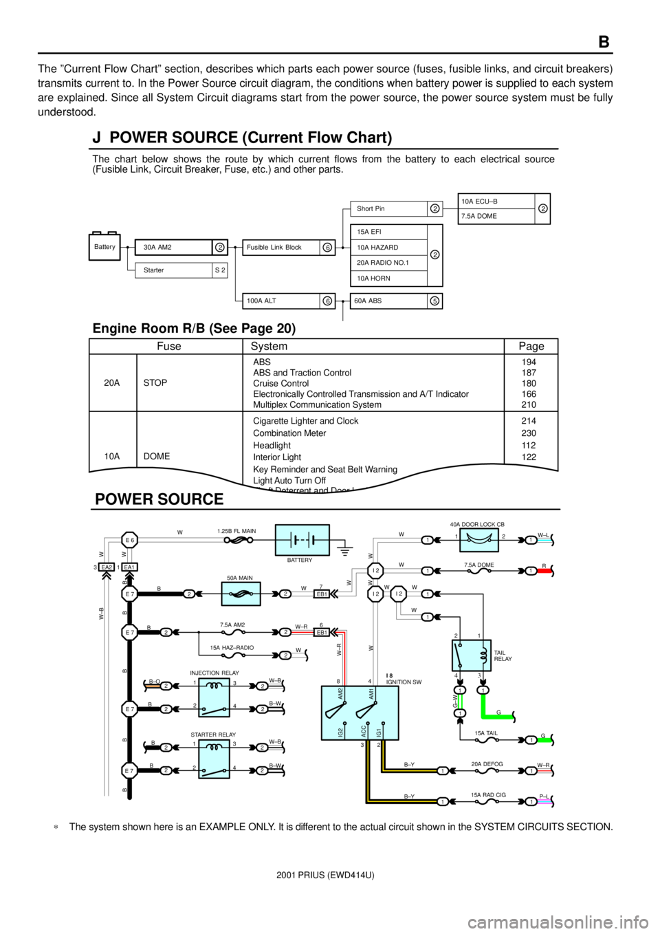
The ºCurrent Flow Chartº section, describes which parts each power source (fuses, fusible links, and circuit breakers)
transmits current to. In the Power Source circuit diagram, the conditions when battery power is supplied to each system
are explained. Since all System Circuit diagrams start from the power source, the power source system must be fully
understood.
Theft Deterrent and Door Lock Control
J POWER SOURCE (Current Flow Chart)
11
1
EA1 1EA2 3
7
EB16
E 6
E 7I 2I 2
I 2
E 7
E 7
E 7
2
1
1
2
2
2
2
2
B
B
W W
B B B B BW±B
B
B
B B±O
B±W
W±B
B±W STARTER RELAY INJECTION RELAY15A HAZ±RADIO7.5A AM250A MAIN 1.25B FL MAIN
BATTERY
WWW
W W W
R W±L
W
W
G±W
G
15A TAIL
20A DEFOG
15A RAD CIGTA I L
RELAY 7.5A DOME 40A DOOR LOCK CB
2 1
1 2
4 8
2 3
3 4
G
W±R
P±L B±Y
B±Y
W±R
AM2 IG2
ACC
IG1AM1W W
W±R
W W
W±B
21
1
1
1
1
2
2
2
2
3
4
3
4 1
2
1
22
1
11
1
IGNITION SW I 8
Battery
30A AM2
2
Starter S 220A RADIO NO.1
10A HORN
15A EFI
7.5A DOMEShort Pin
10A HAZARD
The chart below shows the route by which current flows from the battery to each electrical source
(Fusible Link, Circuit Breaker, Fuse, etc.) and other parts.
Engine Room R/B (See Page 20)
ABS
ABS and Traction Control
Cruise Control
Electronically Controlled Transmission and A/T Indicator
Multiplex Communication System
Cigarette Lighter and Clock
Key Reminder and Seat Belt Warning STOP
Fuse Page
194
214
11 2
System
DOME 20A
10ACombination Meter
Headlight
Interior Light
2
2
6 100A ALT
EB1
POWER SOURCE
Light Auto Turn Off187
180
166
210
230
122
10A ECU±B
5 60A ABS
2
6 Fusible Link Block2
*The system shown here is an EXAMPLE ONLY. It is different to the actual circuit shown in the SYSTEM CIRCUITS SECTION.
Page 35 of 1943

2001 PRIUS (EWD414U)
G
Position of Parts in Engine Compartment
I 1 Ignition Coil and Igniter No.1
I 2 Ignition Coil and Igniter No.2
I 3 Ignition Coil and Igniter No.3
I 4 Ignition Coil and Igniter No.4
I 5 Injector No.1
I 6 Injector No.2
I 7 Injector No.3
I 8 Injector No.4
I 9 Inverter
I 10 Inverter
I 11 Inverter
I 12 Inverter
I 13 Inverter
I 14 Inverter
K 1 Knock Sensor
M 1 Mass Air Flow Meter
M 2 Motor Generator No.1
M 3 Motor Generator No.2
M 4 Motor Generator No.2N 1 Noise Filter (Ignition)
O 1 Oil Pressure SW
R 1 Radiator Fan Motor
S 1 Steering Shaft Torque Sensor
T 1 Theft Deterrent Horn
T 2 Throttle Control Motor
T 3 Throttle Position Sensor
V 1 Vacuum Sensor (HC Adsorber and Catalyst System)
V 2 VSV (EVAP)
V 3 VSV (HC Adsorber and Catalyst System)
W 1 Washer Motor
W 2 Water Pump Motor (A/C)
W 3 Water Pump Motor (Inverter)
W 4 Water Temp. SW
Page 52 of 1943
2001 PRIUS (EWD414U)
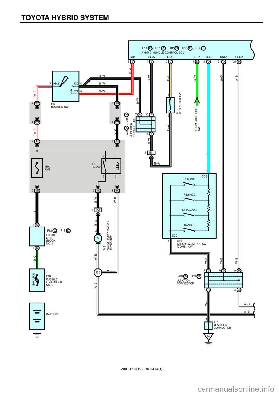
TOYOTA HYBRID SYSTEM
C 1
1D1B 215A
AM2 1J 9ST2IG2 AM2 6
BATTERY7
IGNITION SW I15
FUSIBLE
LINK
BLOCK
NO. 1D F1 2 , F13C
B±G B W±R W±R
2C 2
2G 1
120A MAIN
1
FUSIBLE
LINK BLOCK
NO. 2 F18A CACE 7
B B
ID1 63 4D 2D16 ST1± IGSW CCS
B±W
B±Y
L LB±W
B±W
E 6ST2
R±W
STOP LIGHT SW S 3
B±W 8
IGA AAAB A B A B AD 31 D24
5
A 4
CRUISE CONTROL SW
[COMB. SW] C14
W±B W±B
W±B
W±BW±B
W±B
D 1STP GND1 GND2
G±W
JUNCTION
CONNECTOR J17
FROM STOP LIGHT
SW
W±B JUNCTION
CONNECTORB J18 , J19A
JUNCTION
CONNECTORB J24 A , J25
H14 , D H13 , E H12 , B CH11, H10 A
HYBRID VEHICLE CONTROL ECU
B±W
CCS
CRUISE
RES/ACC
SET/COAST
CANCEL 11 2G52B
1J 3
32 51
1A 21K3
IK1 14
M
1 2
E 5
B±W B±W B±W
W±B W±B W±B
W± B
WATER PUMP MOTOR
(
INVERTER) W 3
IG2
RELAYB±W
B±W
R±W
W±B ECC
Page 66 of 1943
2001 PRIUS (EWD414U)
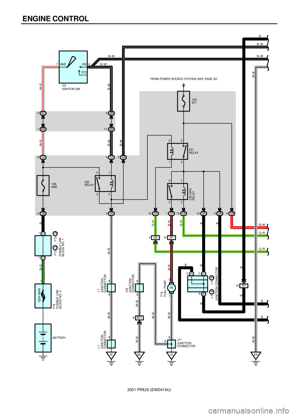
ENGINE CONTROL
120A MAIN
1C 1
D 11B 215A
AM2 1J 92C 2
2G 176AM2 IG2
ST2
32 512B 5
2G 11
1J 3
1K 3
BL 1A 2
EA 15A
EFI
32 51
1F 11A10 1A31A4 13 25
1F 12 1F13
IA2 4IA114
7 3
IGA C
B AIA1 19 A
AA A
FUSIBLE LINK
BLOCK NO. 2 F18
JUNCTION CONNECTORB J 4 A , J 5FUSIBLE LINK
BLOCK NO. 1D F1 2 C , F13
W±BW±B W±B W±BB±G B W±R W±R
B±W B±W
B±W
B B G±RB±R G±R
B±R
B B
BB
W±B
B
B±W
B±W
R±W
G± R
G± R
B
B B±W
B±W
A C
FUEL PUMP F1 6
CIR OPN
RELAY
EFI
RELAY FROM POWER SOURCE SYSTEM (
SEE PAGE 50)
IGNITION SW I15
IG2
RELAY
JUNCTION
CONNECTOR J17B
BATTERY
JUNCTION
CONNECTOR J 7
JUNCTION
CONNECTOR J 1
A
A
JUNCTION
CONNECTOR
IEBC1 8
A
W±BJ18
W±B W±B
M
Page 68 of 1943
2001 PRIUS (EWD414U)
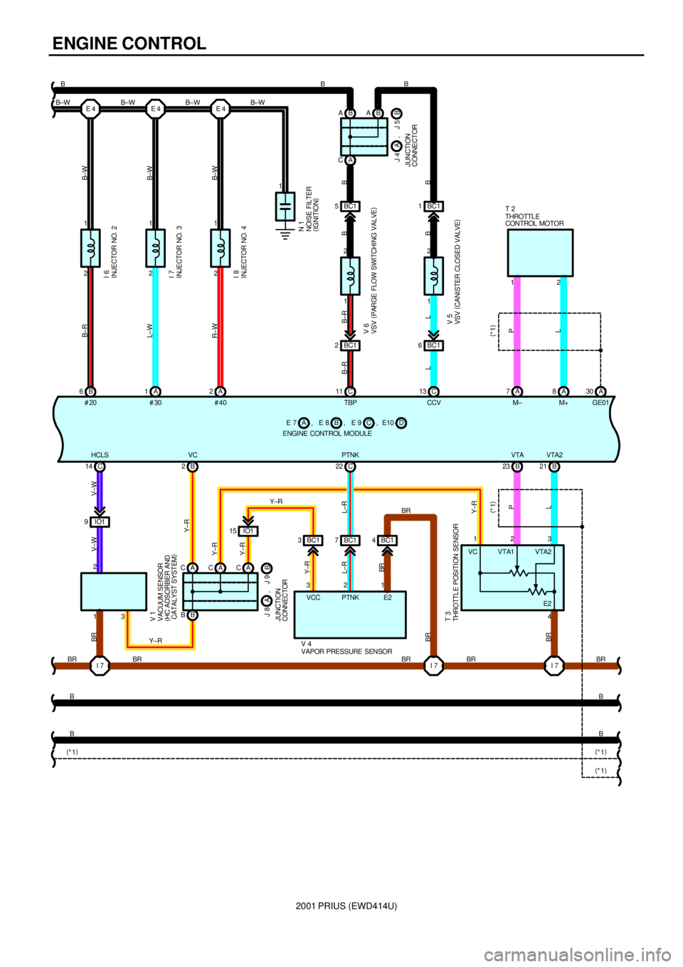
ENGINE CONTROL
2 1
B 62 1
A 1A1
2
2 E 4E 4E 4
1
I 7 IO1 9C 14
B BB 2
A CACACB 23 B21
I 7 IO1 15
BC1 3BC17BC14 C 22
I 7 B ABA
A C
BC1 5
BC1 2
C 11BC1 1
BC1 6
C 13 A7A8A30 12
1 1
134 23 1
1 2 3 22 2
B±R
L±W
R±W B±WB±W
B±W
V±W V±W BR
BR L±R Y±RY±R Y±RY±R
B±R
LLB±R B
BB
B
P
L (
*1)
BR BRL±R
BR
B
B BR
B
BBRBR BR B±WBBB
B±W B±W B±W
P
L (
*1)
THROTTL E
CONTROL MOTOR T 2
VAPOR PRESSURE SENSOR V 4
VSV (
CANISTER CLOSED VALVE) V 5 VSV (
PARGE FLOW SWITCHING VALVE) V 6NOISE FILTER
(
IGNITION) N 1 INJECTOR NO. 4 I 8 INJECTOR NO. 3 I 7 INJECTOR NO. 2 I 6
VACUUM SENSOR
(
HC ADSORBER AND
CATALYST SYSTEM) V 1
THROTTLE POSITION SENSOR T 3 JUNCTION
CONNECTORB J 8
A, J 9
JUNCTION
CONNECTORB J 4 A , J 5
VTA2 VTA PTNK VC HCLS
Y±RY±RGE01 M+ M± CCV TBP #40 #30 #20
(
*1)
(
*1) (
*1)
Y±RBR E10 , D C , E 9 AE 8, E 7 B
ENGINE CONTROL MODULE
VCC PTNK E2VTA2 VTA1
E2 VC
Page 72 of 1943

2001 PRIUS (EWD414U)
ENGINE CONTROL
This system utilizes an engine control module and maintains overall control of the engine, transmission and so on. An outline
of the engine control is explained here.
1. INPUT SIGNALS
(1) Engine coolant temp. signal circuit
The engine coolant temp. sensor detects the engine coolant temp. and has a built±in thermistor with a resistance which
varies according to the engine coolant temp. thus the engine coolant temp. is input in the form of a control signal into
TERMINAL THW of the engine control module.
(2) Intake air temp. signal circuit
The intake air temp. sensor is installed in the mass air flow meter and detects the intake air temp., which is input as a
control signal into TERMINAL THA of the engine control module.
(3) Oxygen sensor signal circuit
The oxygen density in the exhaust gases is detected and input as a control signal into TERMINALS OX1A and OX1B of
the engine control module.
(4) RPM signal circuit
Camshaft position and crankshaft position are detected by the camshaft position sensor and crankshaft position sensor.
Camshaft position is input as a control signal to TERMINAL G2 of the engine control module, and engine RPM is input
into TERMINAL NE+.
(5) Throttle signal circuit
The throttle position sensor detects the throttle valve opening angle, which is input as a control signal into TERMINALS
VTA and VTA2 of the engine control module.
(6) Vehicle speed signal circuit
The vehicle speed signal from brake ECU, detects the vehicle speed and inputs a control signal into TERMINAL SPD of
the engine control module via the combination meter.
(7) Battery signal circuit
Voltage is constantly applied to TERMINAL BATT of the engine control module. When the ignition SW is turned on, the
voltage for engine control module start±up power supply is applied to TERMINAL +B of the engine control module via
EFI relay.
(8) Engine knock signal circuit
Engine knocking is detected by knock sensor and the signal is input into TERMINAL KNK1 of the engine control module
as a control signal.
2. CONTROL SYSTEM
*SFI system
The SFI system monitors the engine condition through the signals, which are input from each sensor to the engine
control module. The best fuel injection volume is decided based on this data and the program memorized by the engine
control module, and the control signal is output to TERMINALS #10, #20, #30 and #40 of the engine control module to
operate the injector. (Inject the fuel). The SFI system produces control of fuel injection operation by the engine control
module in response to the driving conditions.
*ESA system
The ESA system monitors the engine condition through the signals, which are input to the engine control module from
each sensor. The best ignition timing is detected according to this data and the memorized data in the engine control
module, and the control signal is output to TERMINALS IGT1, IGT2, IGT3 and IGT4. This signal controls the ignition coil
and igniter to provide the best ignition timing for the driving conditions.
*Fuel pump control system
The engine control module operation outputs to TERMINAL FC and controls the CIR OPN relay. Thus controls the fuel
pump drive speed in response to conditions.
3. DIAGNOSIS SYSTEM
With the diagnosis system, when there is a malfunctioning in the engine control module signal system, the malfunction
system is recorded in the memory. The malfunctioning system can then be found by reading the display (Code) of the
malfunction indicator lamp.
4. FAIL±SAFE SYSTEM
When a malfunction occurs in any system, if there is a possibility of engine trouble being caused by continued control based
on the signals from that system, the fail±safe system either controls the system by using data (Standard values) recorded in
the engine control module memory or else stops the engine.
SYSTEM OUTLINE
Page 76 of 1943
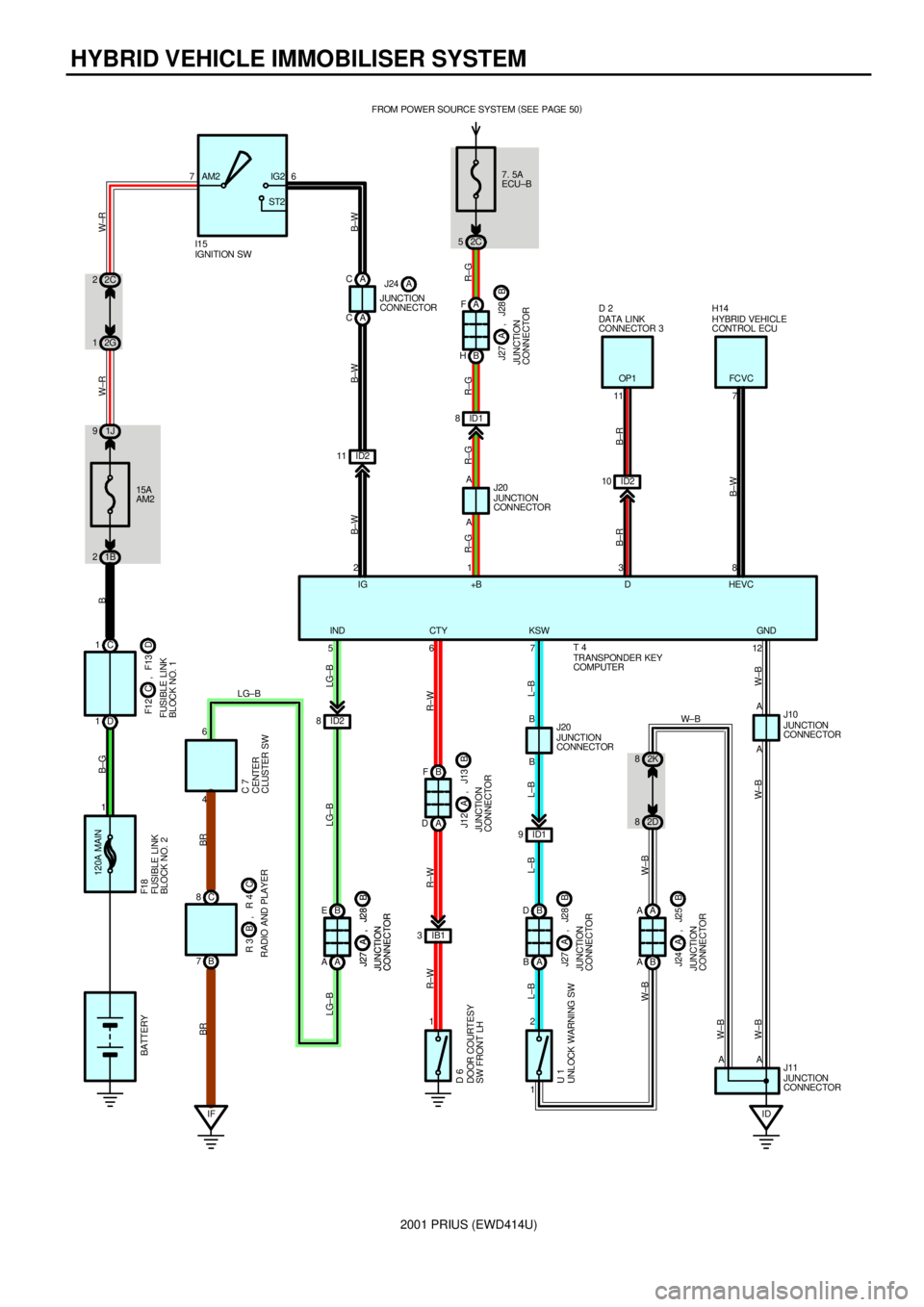
2001 PRIUS (EWD414U)
HYBRID VEHICLE IMMOBILISER SYSTEM
7. 5A
ECU±B FROM POWER SOURCE SYSTEM (
SEE PAGE 50)
2C 5
A A AA F
B H
5JUNCTION
CONNECTOR J20
JUNCTION
CONNECTOR J11 1
12
R±G R±G R±G LG±B
W±B W± B W±B
+B HEVC
IND
JUNCTION
CONNECTORB J27 A , J28
ID2 10 ID2 11 76
15A
AM2
1B 21J 92C 2
2G 1
D 1C 1
120A MAIN
1AM2 IG2
ST2
IFC 8
B 7B E
A A
JUNCTION
CONNECTORB J27 A , J28
JUNCTION
CONNECTORB J27 A , J28
B F
A D
JUNCTION
CONNECTORB J12 A , J13
B D
A B
JUNCTION
CONNECTORB J27 A , J28
A A
B A
JUNCTION
CONNECTORB J24 A , J25
ID A A
2D 8
1 2ID1 9B B
IB1 3
1 ID2 8
JUNCTION
CONNECTOR J10
JUNCTION
CONNECTOR J20
46711 7
238
6DATA LINK
CONNECTOR 3 D 2
HYBRID VEHICLE
CONTROL ECU H14
CENTER
CLUSTER SW C 7
DOOR COURTESY
SW FRONT LH D 6
UNLOCK WARNING SW U 1RADIO AND PLAYERC R 3 B , R 4FUSIBLE LINK
BLOCK NO. 1D F1 2 C , F13 BATTERYB±G B W±R W±R
B±W B±W B±W
B±R
B±WB±R R±W
L±B
W±BL±B L±B L±B
W±BR±W R±WLG±B BR BR
LG±B
2K 8
A IG D
KSW CTY
LG±B
FUSIBLE LINK
BLOCK NO. 2 F18
W±B
W± B ID1 8
R±G
IGNITION SW I15
OP1 FC VC
GND
TRANSPONDER KEY
COMPUTER T 4 A C
A CJUNCTION
CONNECTORJ24 A