Page 301 of 1943
ENGINE ± 1NZ-FXE ENGINE
182EG20
182EG21
From Air Cleaner To Intake Air Chamber
When the Tank is Full
From Air CleanerTo Intake Air Chamber
When the Tank is EmptyVapor Reducing Fuel Tank 60
� System Diagram �
Fuel Gauge
�A direct-acting fuel gauge has been provided in the sub tank.
�This gauge consists of a pipe that is surrounded by a coil, and a float in the pipe moves up and down with
the fluctuation of the fuel level.
A magnet is attached to the back side of the float. The up or down movement of the float causes a change
in the magnetic field. The flow of current through the coil creates a potential difference, and the resultant
voltage is transmitted to the meter ECU. For details, see page 146 (Meter Section).
Page 311 of 1943
ENGINE ± 1NZ-FXE ENGINE
185EG10
ECM
Oil Pressure 70
3) Hold
The ECM calculates the target timing angle according to the traveling state to perform control as de-
scribed in the previous page. After setting at the target timing, the valve timing is held by keeping the
camshaft timing oil control valve in the neutral position unless the traveling state changes.
This adjusts the valve timing at the desired target position and prevents the engine oil from running out
when it is unnecessary.
Page 349 of 1943

CHASSIS ± P111 HYBRID TRANSAXLE
182CH22
Oil Pump Drive
Shaft
Oil Pump Drive
Rotor
Oil Pump
Driven
Rotor
182CH23
182CH24
Parking Gear
Parking
Lock
Pawl
Link 1
Link 2
ªAº View Link 2
Parking Rod
Parking
Lock
Pawl ªAº View87
�LUBRICATION SYSTEM
A force-feed lubrication system using a trocoid
pump has been adopted for lubrication of the plan-
etary gear unit and the bearings on the main shaft.
The oil pump is directly driven by the engine.
The same type of oil is used for both the reduction
unit portion and the differential portion.
�PARKING LOCK MECHANISM
A mechanical parking lock mechanism has been
provided in the counter driven gear.
The engagement of the parking lock pawl with the
parking gear that is integrated with the counter
driven gear locks the movement of the vehicle.
The direction of the parking lock pawl changes via
the two link mechanisms that are connected to the
outer lever through the shift cable. The longitudi-
nal movement of the parking rod causes a vertical
movement of the parking lock pawl that meshes
with the parking gear.
Page 414 of 1943

BODY ELECTRICAL ± AIR CONDITIONING 152
AIR CONDITIONING
�DESCRIPTION
The air conditioning system in the Prius has the following features:
�Both heating and demisting performances are realized by adopting performances are realized by adopting
the 2-way flow heater type air conditioning unit.
�A multi-tank, super-slim structure evaporator has been adopted.
�An automatic air conditioning system which provides enhanced air conditioning comfort according to the
occupant's senses has been adopted.
�A semi-center location air conditioning unit, in which the evaporator and heater core are placed in the ve-
hicle's longitudinal direction, has been adopted.
�A compact, high-performance scroll compressor with oil separator has been adopted.
�The heat exchange efficiency has been improved through the adoption of the sub-cool condenser.
This condenser is integrated with the radiator to minimize the space they occupy in the engine compart-
ment.
�A compact, lightweight, and highly efficient straight flow (full-path flow) aluminium heater core has been
adopted.
This heater core is integrated with a PTC (Positive Temperature Coefficient) heater, which excels in heat-
ing performance.
�PTC heaters have been provided in the air duct at the footwell outlet in front of the air conditioning unit.
However, air conditioning without the PTC heaters is offered as an option on the U.S.A. models.
�An electrical water pump with a bypass valve that provides a stable heater performance even if the engine
is stopped due to a function of the THS (TOYOTA Hybrid System) has been adopted.
�A clean air filter that excels in removing pollen and dust is standard equipment.
Page 531 of 1943
PP2FL±03
± PREPARATIONLUBRICATION
PP±17
2001 PRIUS (RM778U)
LUBRICANT
ItemCapacityClassification
Engine oil
Drain and refill w/ Oil filter change
w/o Oil filter change
Dry fill
3.7 liters (3.9 US qts, 3.3 lmp.qts)
3.4 liters (3.6 US qts, 3.0 lmp.qts)
4.1 liters (4.3 US qts, 3.6 lmp.qts)API grade SJ, Energy±Conserving or ILSAC mul-
tigrade engine oil. SAE 5W±30 is the best choice
for your vehicle, for good fuel economy,and good
starting in cold weather.
Page 679 of 1943
DI±76
± DIAGNOSTICSENGINE
2001 PRIUS (RM778U)
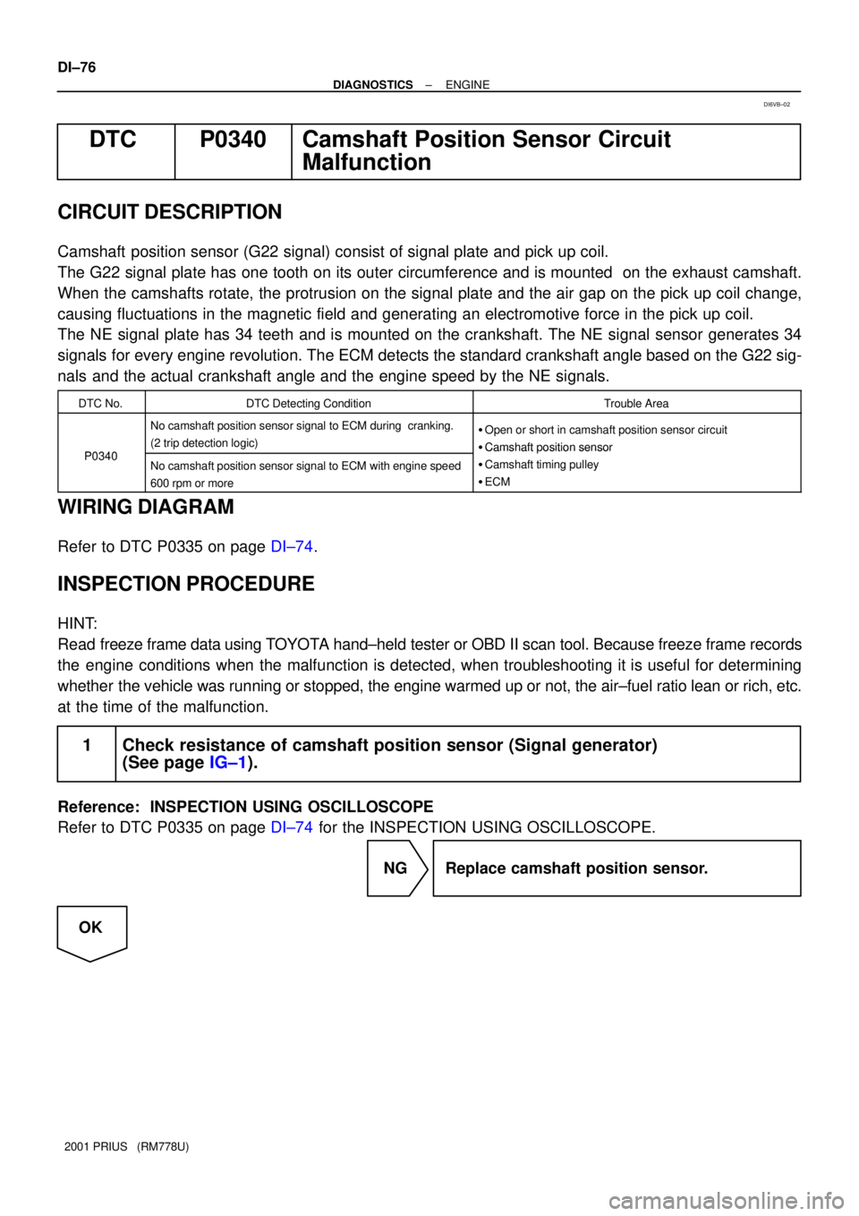
DTC P0340 Camshaft Position Sensor Circuit
Malfunction
CIRCUIT DESCRIPTION
Camshaft position sensor (G22 signal) consist of signal plate and pick up coil.
The G22 signal plate has one tooth on its outer circumference and is mounted on the exhaust camshaft.
When the camshafts rotate, the protrusion on the signal plate and the air gap on the pick up coil change,
causing fluctuations in the magnetic field and generating an electromotive force in the pick up coil.
The NE signal plate has 34 teeth and is mounted on the crankshaft. The NE signal sensor generates 34
signals for every engine revolution. The ECM detects the standard crankshaft angle based on the G22 sig-
nals and the actual crankshaft angle and the engine speed by the NE signals.
DTC No.DTC Detecting ConditionTrouble Area
P0340
No camshaft position sensor signal to ECM during cranking.
(2 trip detection logic)�Open or short in camshaft position sensor circuit
�Camshaft position sensor
P0340No camshaft position sensor signal to ECM with engine speed
600 rpm or more
�Camshaft osition sensor
�Camshaft timing pulley
�ECM
WIRING DIAGRAM
Refer to DTC P0335 on page DI±74.
INSPECTION PROCEDURE
HINT:
Read freeze frame data using TOYOTA hand±held tester or OBD II scan tool. Because freeze frame records
the engine conditions when the malfunction is detected, when troubleshooting it is useful for determining
whether the vehicle was running or stopped, the engine warmed up or not, the air±fuel ratio lean or rich, etc.
at the time of the malfunction.
1 Check resistance of camshaft position sensor (Signal generator)
(See page IG±1).
Reference: INSPECTION USING OSCILLOSCOPE
Refer to DTC P0335 on page DI±74 for the INSPECTION USING OSCILLOSCOPE.
NG Replace camshaft position sensor.
OK
DI6VB±02
Page 721 of 1943
A09060
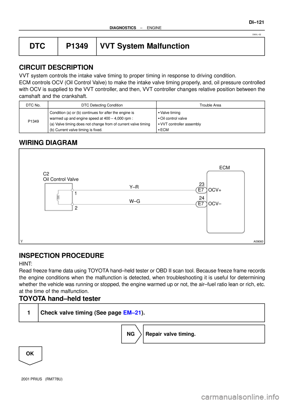
C2
Oil Control Valve
2 1Y±R
W±GECM
OCV+
OCV± 23
24
E7 E7
± DIAGNOSTICSENGINE
DI±121
2001 PRIUS (RM778U)
DTC P1349 VVT System Malfunction
CIRCUIT DESCRIPTION
VVT system controls the intake valve timing to proper timing in response to driving condition.
ECM controls OCV (Oil Control Valve) to make the intake valve timing properly, and, oil pressure controlled
with OCV is supplied to the VVT controller, and then, VVT controller changes relative position between the
camshaft and the crankshaft.
DTC No.DTC Detecting ConditionTrouble Area
P1349
Condition (a) or (b) continues for after the engine is
warmed up and engine speed at 400 ± 4,000 rpm :
(a) Valve timing does not change from of current valve timing
(b) Current valve timing is fixed.�Valve timing
�Oil control valve
�VVT controller assembly
�ECM
WIRING DIAGRAM
INSPECTION PROCEDURE
HINT:
Read freeze frame data using TOYOTA hand±held tester or OBD II scan tool. Because freeze frame records
the engine conditions when the malfunction is detected, when troubleshooting it is useful for determining
whether the vehicle was running or stopped, the engine warmed up or not, the air±fuel ratio lean or rich, etc.
at the time of the malfunction.
TOYOTA hand±held tester
1 Check valve timing (See page EM±21).
NG Repair valve timing.
OK
DI6VL±02
Page 722 of 1943
A02397
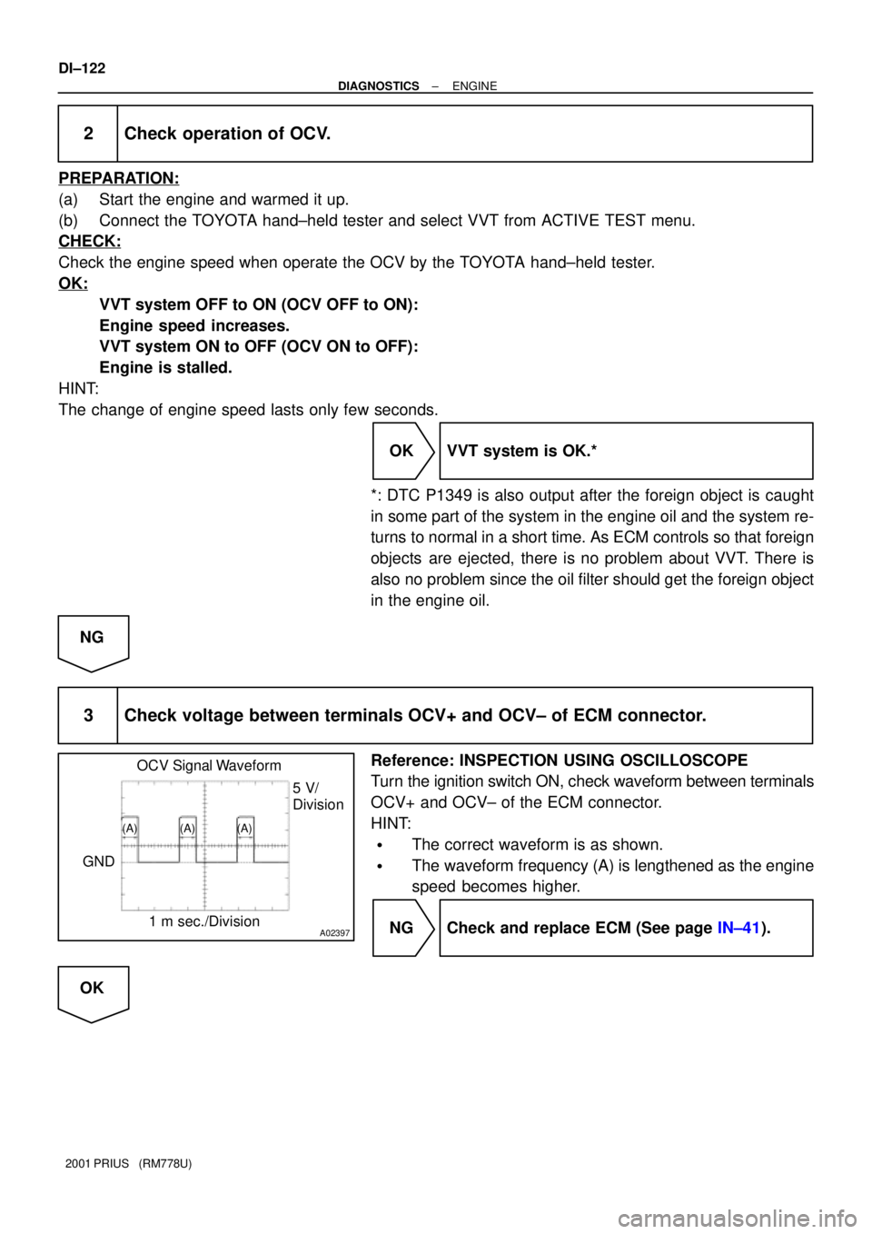
OCV Signal Waveform
1 m sec./Division5 V/
Division
GND
(A) (A) (A)
DI±122
± DIAGNOSTICSENGINE
2001 PRIUS (RM778U)
2 Check operation of OCV.
PREPARATION:
(a) Start the engine and warmed it up.
(b) Connect the TOYOTA hand±held tester and select VVT from ACTIVE TEST menu.
CHECK:
Check the engine speed when operate the OCV by the TOYOTA hand±held tester.
OK:
VVT system OFF to ON (OCV OFF to ON):
Engine speed increases.
VVT system ON to OFF (OCV ON to OFF):
Engine is stalled.
HINT:
The change of engine speed lasts only few seconds.
OK VVT system is OK.*
*: DTC P1349 is also output after the foreign object is caught
in some part of the system in the engine oil and the system re-
turns to normal in a short time. As ECM controls so that foreign
objects are ejected, there is no problem about VVT. There is
also no problem since the oil filter should get the foreign object
in the engine oil.
NG
3 Check voltage between terminals OCV+ and OCV± of ECM connector.
Reference: INSPECTION USING OSCILLOSCOPE
Turn the ignition switch ON, check waveform between terminals
OCV+ and OCV± of the ECM connector.
HINT:
�The correct waveform is as shown.
�The waveform frequency (A) is lengthened as the engine
speed becomes higher.
NG Check and replace ECM (See page IN±41).
OK