Page 949 of 1943
DI7OK±01
BR3583
BR3582F00010
RotorSpeed Sensor
Magnet
To ECU
+V
±VHigh Speed
Low Speed
CoilNS
± DIAGNOSTICSANTI±LOCK BRAKE SYSTEM WITH EBD & RBS
DI±371
2001 PRIUS (RM778U)
CIRCUIT INSPECTION
DTC
C0200/31 ± C0215/34Speed Sensor Circuit
CIRCUIT DESCRIPTION
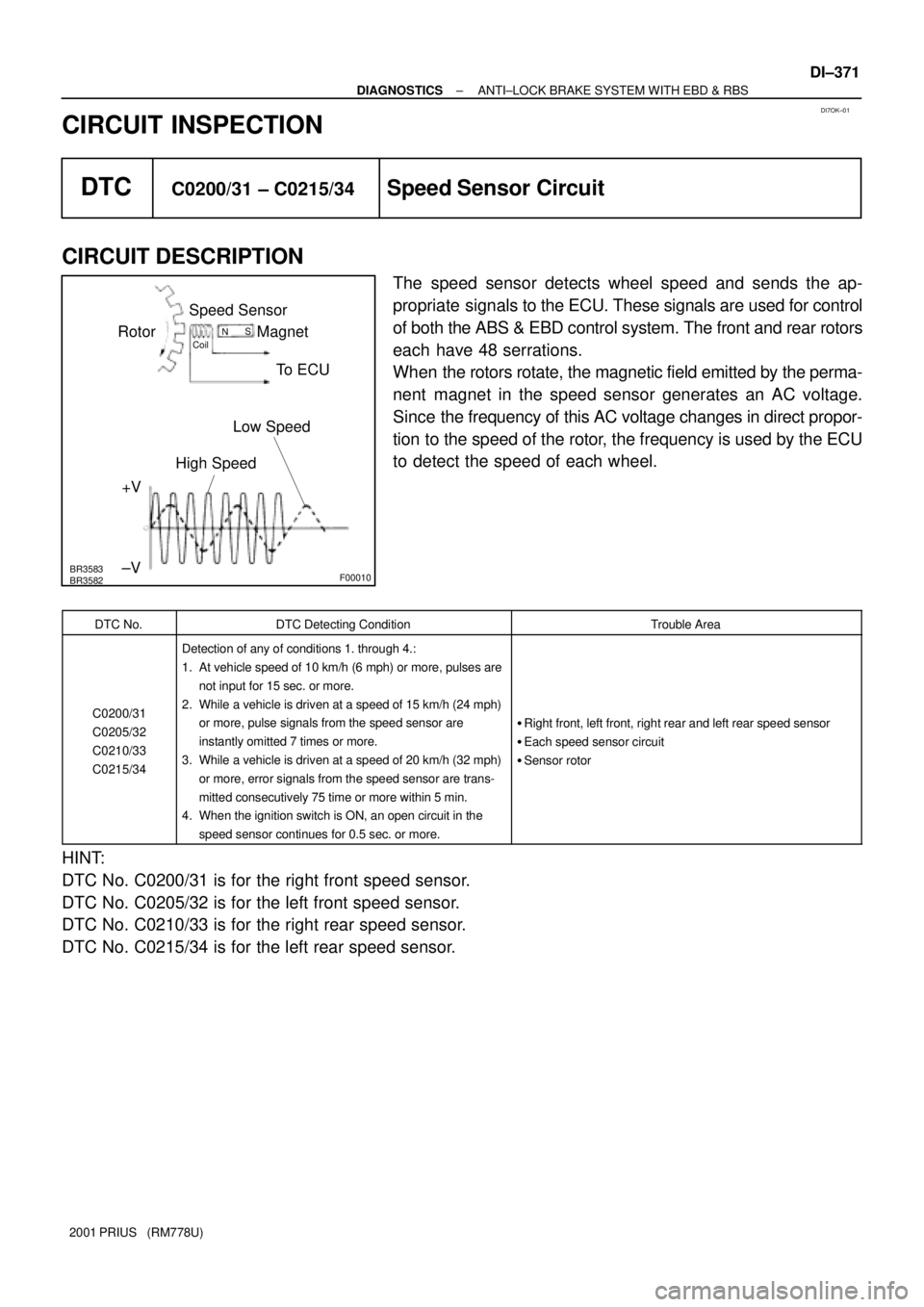
The speed sensor detects wheel speed and sends the ap-
propriate signals to the ECU. These signals are used for control
of both the ABS & EBD control system. The front and rear rotors
each have 48 serrations.
When the rotors rotate, the magnetic field emitted by the perma-
nent magnet in the speed sensor generates an AC voltage.
Since the frequency of this AC voltage changes in direct propor-
tion to the speed of the rotor, the frequency is used by the ECU
to detect the speed of each wheel.
DTC No.DTC Detecting ConditionTrouble Area
C0200/31
C0205/32
C0210/33
C0215/34
Detection of any of conditions 1. through 4.:
1. At vehicle speed of 10 km/h (6 mph) or more, pulses are
not input for 15 sec. or more.
2. While a vehicle is driven at a speed of 15 km/h (24 mph)
or more, pulse signals from the speed sensor are
instantly omitted 7 times or more.
3. While a vehicle is driven at a speed of 20 km/h (32 mph)
or more, error signals from the speed sensor are trans-
mitted consecutively 75 time or more within 5 min.
4. When the ignition switch is ON, an open circuit in the
speed sensor continues for 0.5 sec. or more.
�Right front, left front, right rear and left rear speed sensor
�Each speed sensor circuit
�Sensor rotor
HINT:
DTC No. C0200/31 is for the right front speed sensor.
DTC No. C0205/32 is for the left front speed sensor.
DTC No. C0210/33 is for the right rear speed sensor.
DTC No. C0215/34 is for the left rear speed sensor.
Page 1582 of 1943
B00319
Recommended Oil Viscosity (SAE):
10W ± 30
5W ± 30 PREFERRED
TEMPERATURE RANGE ANTICIPATED BEFORE NEXT OIL CHANGE100
38 80 60
27 40
16 0
±720
4 ±18 ±20
±29
°C °F
LU02K±08
B11764
Oil Pressure
Switch
B11765
Oil Pressure Gauge
± LUBRICATIONOIL AND FILTER
LU±1
1307 Author�: Date�:
2001 PRIUS (RM778U)
OIL AND FILTER
INSPECTION
1. CHECK ENGINE OIL QUALITY
Check the oil for deterioration, entry of water, discoloring or thin-
ning.
If the quality is visibly poor, replace the oil.
Oil grade:
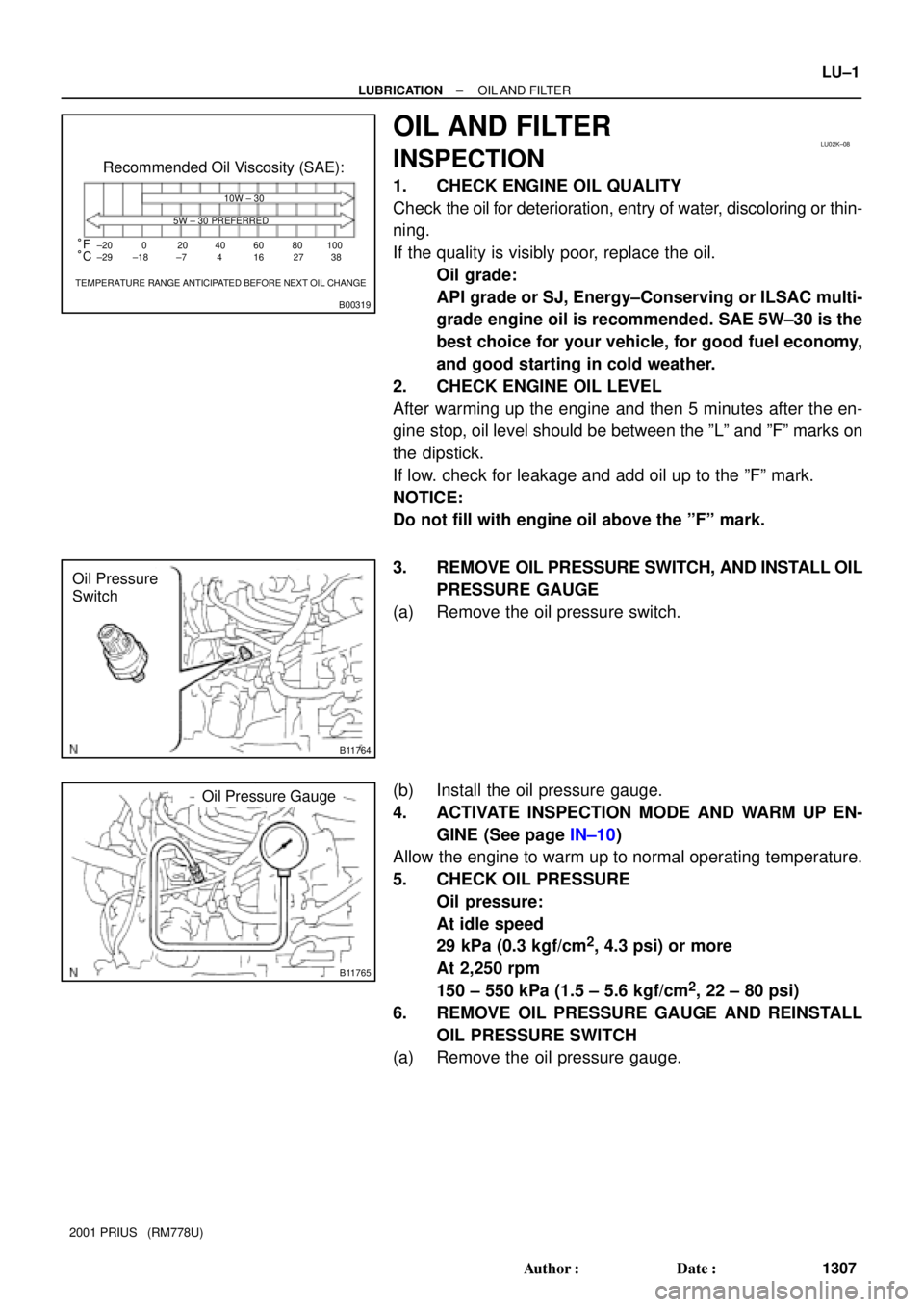
API grade or SJ, Energy±Conserving or ILSAC multi-
grade engine oil is recommended. SAE 5W±30 is the
best choice for your vehicle, for good fuel economy,
and good starting in cold weather.
2. CHECK ENGINE OIL LEVEL
After warming up the engine and then 5 minutes after the en-
gine stop, oil level should be between the ºLº and ºFº marks on
the dipstick.
If low. check for leakage and add oil up to the ºFº mark.
NOTICE:
Do not fill with engine oil above the ºFº mark.
3. REMOVE OIL PRESSURE SWITCH, AND INSTALL OIL
PRESSURE GAUGE
(a) Remove the oil pressure switch.
(b) Install the oil pressure gauge.
4. ACTIVATE INSPECTION MODE AND WARM UP EN-
GINE (See page IN±10)
Allow the engine to warm up to normal operating temperature.
5. CHECK OIL PRESSURE
Oil pressure:
At idle speed
29 kPa (0.3 kgf/cm
2, 4.3 psi) or more
At 2,250 rpm
150 ± 550 kPa (1.5 ± 5.6 kgf/cm
2, 22 ± 80 psi)
6. REMOVE OIL PRESSURE GAUGE AND REINSTALL
OIL PRESSURE SWITCH
(a) Remove the oil pressure gauge.
Page 1588 of 1943
CHECK POWER SUPPLY TO IGNITION COIL (WITH
SENSOR (See step 3)
SPARK TEST
Replace the crankshaft position sensor.
CHECK RESISTANCE OF CAMSHAFT POSITION
1. Turn ignition switch to ON.
2. Check that there is battery voltage at ignition coil positive (+)
terminal.
CHECK CONNECTION OF IGNITION COIL
CONNECTOR
Resistance:Cold Hot
CHECK RESISTANCE OF CRANKSHAFT POSITION
Resistance:Cold Hot 1,630 ± 2,740 W2,065 ± 3.225 W
CHECK IGT SIGNAL FROM ECM
(See page
DI±115)
TRY ANOTHER IGNITION COIL (WITH IGNITER)
Replace the camshaft position sensor. Connect securely.
Check wiring between ignition switch
to ignition coil (with igniter).
Check wiring between ECM and ignition
coil (with igniter), and then try another ECM.
NO
OK
OK
OK
OKBAD
BAD
BAD
BAD
BAD
SENSOR (See step 4) IGNITER) CHANGE IT TO NORMAL IGNITION COIL (WITH
IGNITER) AND PERFORM SPARK TEST AGAIN
OKReplace the ignition coil (with igniter).
NO
OK
985 ± 1,600 W1,265 ± 1,890 W
B11755
16 mm (0.63 in.)
Plug Wrench IG±2
± IGNITIONIGNITION SYSTEM
1319 Author�: Date�:
2001 PRIUS (RM778U)
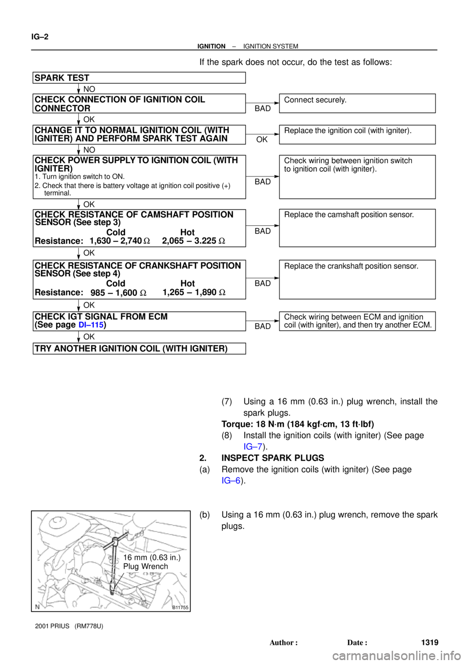
If the spark does not occur, do the test as follows:
(7) Using a 16 mm (0.63 in.) plug wrench, install the
spark plugs.
Torque: 18 N´m (184 kgf´cm, 13 ft´lbf)
(8) Install the ignition coils (with igniter) (See page
IG±7).
2. INSPECT SPARK PLUGS
(a) Remove the ignition coils (with igniter) (See page
IG±6).
(b) Using a 16 mm (0.63 in.) plug wrench, remove the spark
plugs.
Page 1789 of 1943
I17865
Fuel Sender Gauge Connector
I17865
Fuel Sender Gauge Connector
I01277
BatteryWarning Light Ignition
Switch
Wire Harness Side
1
I01278
BE±44
± BODY ELECTRICALCOMBINATION METER
2001 PRIUS (RM778U)
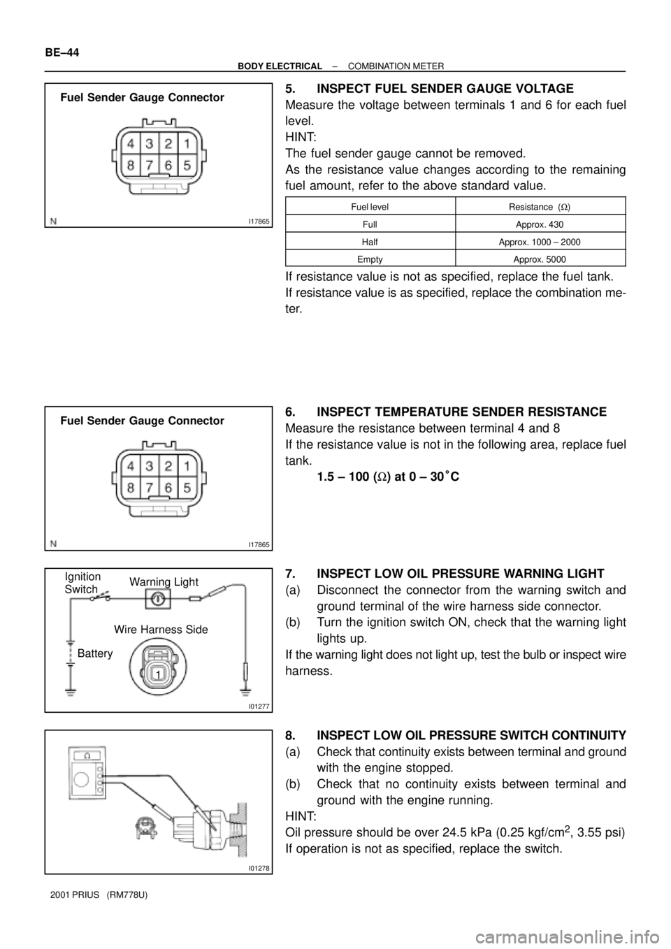
5. INSPECT FUEL SENDER GAUGE VOLTAGE
Measure the voltage between terminals 1 and 6 for each fuel
level.
HINT:
The fuel sender gauge cannot be removed.
As the resistance value changes according to the remaining
fuel amount, refer to the above standard value.
Fuel levelResistance (W)
FullApprox. 430
HalfApprox. 1000 ± 2000
EmptyApprox. 5000
If resistance value is not as specified, replace the fuel tank.
If resistance value is as specified, replace the combination me-
ter.
6. INSPECT TEMPERATURE SENDER RESISTANCE
Measure the resistance between terminal 4 and 8
If the resistance value is not in the following area, replace fuel
tank.
1.5 ± 100 (W) at 0 ± 30°C
7. INSPECT LOW OIL PRESSURE WARNING LIGHT
(a) Disconnect the connector from the warning switch and
ground terminal of the wire harness side connector.
(b) Turn the ignition switch ON, check that the warning light
lights up.
If the warning light does not light up, test the bulb or inspect wire
harness.
8. INSPECT LOW OIL PRESSURE SWITCH CONTINUITY
(a) Check that continuity exists between terminal and ground
with the engine stopped.
(b) Check that no continuity exists between terminal and
ground with the engine running.
HINT:
Oil pressure should be over 24.5 kPa (0.25 kgf/cm
2, 3.55 psi)
If operation is not as specified, replace the switch.