Page 1212 of 1943
I19096
ON
STP
(+) (±)
DI±656
± DIAGNOSTICSCRUISE CONTROL SYSTEM
2001 PRIUS (RM778U)
INSPECTION PROCEDURE
1 Check operation of stop light.
CHECK:
Check that stop light comes on when brake pedal is depressed, and turns off when brake pedal is released.
NG Check stop light system (See page BE±2).
OK
2 Check voltage between terminal STP of hybrid vehicle control ECU connector
and body ground.
PREPARATION:
(a) Remove the hybrid vehicle control ECU with connectors
still connected.
(b) Turn ignition switch ON.
CHECK:
Measure voltage between terminal STP of hybrid vehicle con-
trol ECU connector and body ground, when the brake pedal is
depressed and released.
OK:
Depressed10 ± 14 V
ReleasedBelow 1 V
OK Proceed to next circuit inspection shown in
problem symptom table (See page DI±648).
NG
Page 1213 of 1943
I19096
ON
ST1±
(+) (±)
± DIAGNOSTICSCRUISE CONTROL SYSTEM
DI±657
2001 PRIUS (RM778U)
3 Check voltage between terminal ST1± of hybrid vehicle control ECU connector
and body ground.
PREPARATION:
(a) Remove the hybrid vehicle control ECU with connectors
still connected.
(b) Turn ignition switch ON.
CHECK:
Measure voltage between terminal ST1± of hybrid vehicle con-
trol ECU connector and body ground, when the brake pedal is
depressed and released.
OK:
DepressedBelow 1 V
Released10 ± 14 V
OK Proceed to next circuit inspection shown in
problem symptoms table (See page DI±648).
NG
4 Check wire harness and connector between terminal STP of hybrid vehicle con-
trol ECU and stop light switch, and terminal ST1± of hybrid vehicle control ECU
and stop light switch (See page IN±41).
NG Repair or replace harness or connector.
OK
Check and replace hybrid vehicle control
ECU (See page DI±174
).
Page 1214 of 1943
± DIAGNOSTICSCRUISE CONTROL SYSTEM
DI±659
2001 PRIUS (RM778U)
Power source circuit
CIRCUIT DESCRIPTION
This circuit provides power to operate the hybrid vehicle control ECU.
WIRING DIAGRAM
See page DI±156.
INSPECTION PROCEDURE
1 Check IGN and EFI fuse.
CHECK:
Check continuity of IGN and EFI fuse.
OK:
Continuity
NG Replace the failure fuse.
OK
2 Check voltage between terminals IGSW, BATT and GND of hybrid vehicle control
ECU connector (See page IN±41).
PREPARATION:
(a) Turn ignition switch OFF.
(b) Disconnect the hybrid vehicle control ECU connector.
CHECK:
Measure voltage between terminals IGSW, BATT and GND
OK:
Voltage: 10 ± 14 V
OK Proceed to next circuit inspection shown in
problem symptoms table (See page DI±648).
NG
DI7NJ±01
Page 1215 of 1943
DI±660
± DIAGNOSTICSCRUISE CONTROL SYSTEM
2001 PRIUS (RM778U)
3 Check wireharness and connector between hybrid vehicle control ECU and body
ground (See page IN±41).
NG Repair or replace wireharness or connector.
OK
Check and repair wireharness and connector
between hybrid vehicle control ECU and bat-
tery (See page IN±41
).
Page 1216 of 1943
I15479
Combination Meter
FL Block No. 1Instrument Panel J/B
to Body ECU 5A AM1IG1
Relay
3
GR±B14
C10
2A
CRUISE 8
W±B
B±G22
C10 L
2K8
2
C11
W±B I15 Ignition SW
AM1
IG1
F11
Battery
ID 10A GAUGE
5
AJ11
J/C 2 1 2B6
2B3
2D6 W
W±G
B±Y
24
B±Y
1F13
1F18
1FL Block No. 2
120A MAIN
100A DC/DC7
2A
1
2H
IH BR
± DIAGNOSTICSCRUISE CONTROL SYSTEM
DI±665
2001 PRIUS (RM778U)
CRUISE MAIN Indicator Light Circuit
CIRCUIT DESCRIPTION
When the cruise control main switch is turned ON, CRUISE MAIN indicator light lights up.
WIRING DIAGRAM
DI7NL±01
Page 1217 of 1943
DI±666
± DIAGNOSTICSCRUISE CONTROL SYSTEM
2001 PRIUS (RM778U)
INSPECTION PROCEDURE
1 Check combination meter (See page BE±2).
NG Replace combination meter.
OK
Check and replace hybrid vehicle control
ECU (See page DI±174).
Page 1225 of 1943
DI±682
± DIAGNOSTICSCOMBINATION METER SYSTEM
2001 PRIUS (RM778U)
4 Check the corresponding switch or ECU.
CHECK:
Check if the corresponding switch or ECU is normal or not.
Ye s
No Corresponding switch or ECU faulty.
Combination meter ECU faulty.
*:
Multiplex communication inputSingle Communication Input
OPEN DOOR WARNINGHI±BEAM INDICATOR
BRAKE WARNINGTURN SIGNAL IND
OUTPUT CONTROL INDICATORSRS WARNING
SHIFT POSITION INDICATORABS WARNING
SEAT BELT WARNINGCHECK ENGINE WARNING
READY INDICATOR
WATER TEMPERATURE WARNING
OIL PRESSURE WARNING
CRUISE CONTROL INDICATOR
TAIL INDICATOR
DISCHARGE WARNING
Page 1765 of 1943

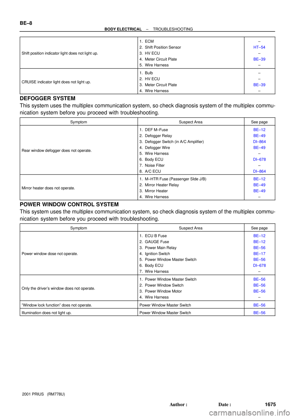
BE±8
± BODY ELECTRICALTROUBLESHOOTING
1675 Author�: Date�:
2001 PRIUS (RM778U) Shift position indicator light does not light up.
1. ECM
2. Shift Position Sensor
3. HV ECU
4. Meter Circuit Plate
5. Wire Harness±
HT±54
±
BE±39
±
CRUISE indicator light does not light up.
1. Bulb
2. HV ECU
3. Meter Circuit Plate
4. Wire Harness±
±
BE±39
±
DEFOGGER SYSTEM
This system uses the multiplex communication system, so check diagnosis system of the multiplex commu-
nication system before you proceed with troubleshooting.
SymptomSuspect AreaSee page
Rear window defogger does not operate.
1. DEF M±Fuse
2. Defogger Relay
3. Defogger Switch (in A/C Amplifier)
4. Defogger Wire
5. Wire Harness
6. Body ECU
7. Noise Filter
8. A/C ECUBE±12
BE±49
DI±864
BE±49
±
DI±678
±
DI±864
Mirror heater does not operate.
1. M±HTR Fuse (Passenger SIde J/B)
2. Mirror Heater Relay
3. Mirror Heater
4. Wire HarnessBE±12
BE±49
BE±49
±
POWER WINDOW CONTROL SYSTEM
This system uses the multiplex communication system, so check diagnosis system of the multiplex commu-
nication system before you proceed with troubleshooting.
SymptomSuspect AreaSee page
Power window dose not operate.
1. ECU B Fuse
2. GAUGE Fuse
3. Power Main Relay
4. Ignition Switch
5. Power Window Master Switch
6. Body ECU
7. Wire HarnessBE±12
BE±12
BE±56
BE±17
BE±56
DI±678
±
Only the driver's window does not operate.
1. Power Window Master Switch
2. Power Window Switch
3. Power Window Motor
4. Wire HarnessBE±56
BE±56
BE±56
±
ºWindow lock functionº does not operate.Power Window Master SwitchBE±56
Illumination does not light up.Power Window Master SwitchBE±56