Page 1934 of 1943
AC36K±01
I18038 : Bulb
5
10
I07872
I17978
1
7
AC±78
± AIR CONDITIONINGHEATER CONTROL ASSEMBLY
2001 PRIUS (RM778U)
INSPECTION
1. INSPECT ILLUMINATION OPERATION
(a) Connect the positive (+) lead from the battery to terminal
5 and negative (±) lead to terminal 10, then check that the
illumination lights up.
If operation is not as specified, check the faulty bulb.
(b) Apply the tester as shown in the illustration to the test for
continuity.
If continuity exists, replace the heater control.
If no continuity exists, replace the bulb.
2. INSPECT INDICATOR OPERATION
Connect the positive (+) lead from the battery to terminal 1 and
negative (±) lead to terminal 7, then check that the illumination
light up.
If operation is not as specified, proceed next inspection.
Page 1935 of 1943

I18039
1
3
2 Dry Cell Batteries
I18040
1
5
2 Dry Cell Batteries
I18043
1 15
2 Dry Cell Batteries
I18044
6 8 14
13
± AIR CONDITIONINGHEATER CONTROL ASSEMBLY
AC±79
2001 PRIUS (RM778U)
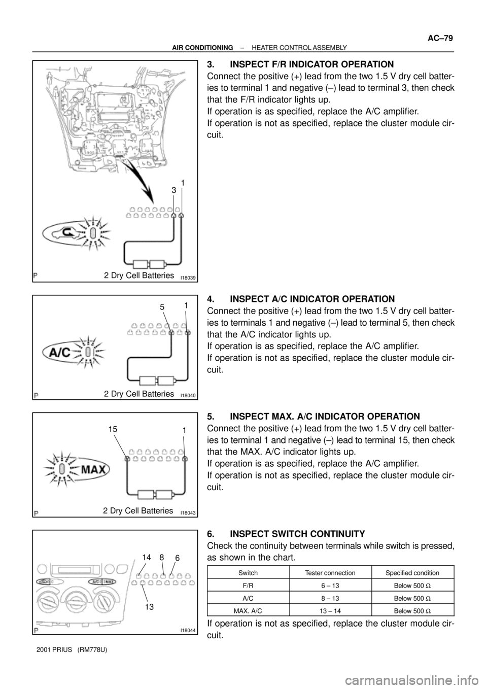
3. INSPECT F/R INDICATOR OPERATION
Connect the positive (+) lead from the two 1.5 V dry cell batter-
ies to terminal 1 and negative (±) lead to terminal 3, then check
that the F/R indicator lights up.
If operation is as specified, replace the A/C amplifier.
If operation is not as specified, replace the cluster module cir-
cuit.
4. INSPECT A/C INDICATOR OPERATION
Connect the positive (+) lead from the two 1.5 V dry cell batter-
ies to terminals 1 and negative (±) lead to terminal 5, then check
that the A/C indicator lights up.
If operation is as specified, replace the A/C amplifier.
If operation is not as specified, replace the cluster module cir-
cuit.
5. INSPECT MAX. A/C INDICATOR OPERATION
Connect the positive (+) lead from the two 1.5 V dry cell batter-
ies to terminal 1 and negative (±) lead to terminal 15, then check
that the MAX. A/C indicator lights up.
If operation is as specified, replace the A/C amplifier.
If operation is not as specified, replace the cluster module cir-
cuit.
6. INSPECT SWITCH CONTINUITY
Check the continuity between terminals while switch is pressed,
as shown in the chart.
SwitchTester connectionSpecified condition
F/R6 ± 13Below 500 W
A/C8 ± 13Below 500 W
MAX. A/C13 ± 14Below 500 W
If operation is not as specified, replace the cluster module cir-
cuit.
Page 1936 of 1943

I180463 Dry Cell Batteries9
12 13
I180473 Dry Cell Batteries9
11 13
COOL
WARM
I180453 Dry Cell Batteries9
10 13 M1
M2
AC±80
± AIR CONDITIONINGHEATER CONTROL ASSEMBLY
2001 PRIUS (RM778U)
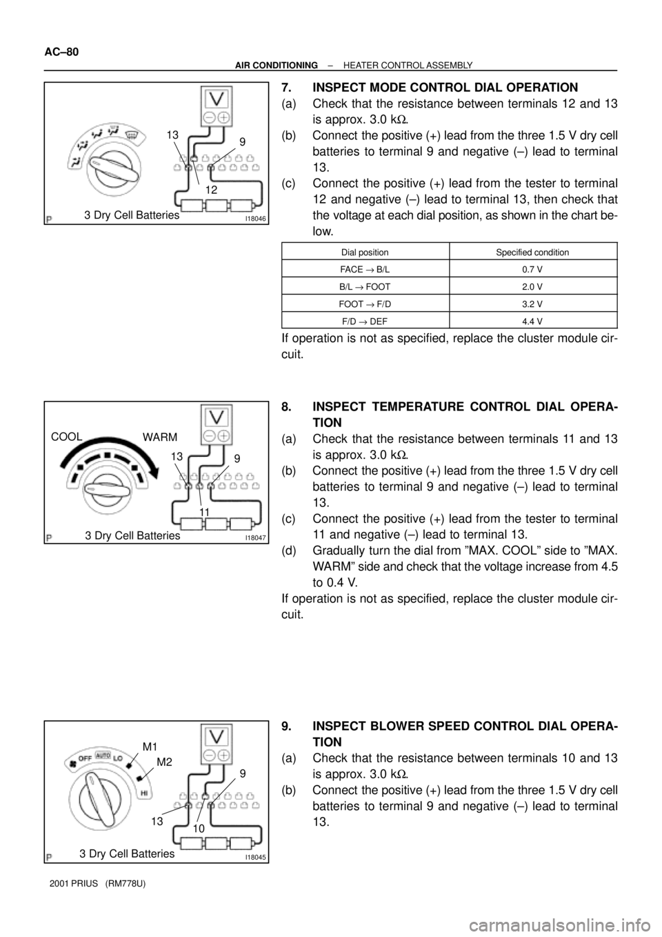
7. INSPECT MODE CONTROL DIAL OPERATION
(a) Check that the resistance between terminals 12 and 13
is approx. 3.0 kW.
(b) Connect the positive (+) lead from the three 1.5 V dry cell
batteries to terminal 9 and negative (±) lead to terminal
13.
(c) Connect the positive (+) lead from the tester to terminal
12 and negative (±) lead to terminal 13, then check that
the voltage at each dial position, as shown in the chart be-
low.
Dial positionSpecified condition
FACE "B/L0.7 V
B/L "FOOT2.0 V
FOOT "F/D3.2 V
F/D " DEF4.4 V
If operation is not as specified, replace the cluster module cir-
cuit.
8. INSPECT TEMPERATURE CONTROL DIAL OPERA-
TION
(a) Check that the resistance between terminals 11 and 13
is approx. 3.0 kW.
(b) Connect the positive (+) lead from the three 1.5 V dry cell
batteries to terminal 9 and negative (±) lead to terminal
13.
(c) Connect the positive (+) lead from the tester to terminal
11 and negative (±) lead to terminal 13.
(d) Gradually turn the dial from ºMAX. COOLº side to ºMAX.
WARMº side and check that the voltage increase from 4.5
to 0.4 V.
If operation is not as specified, replace the cluster module cir-
cuit.
9. INSPECT BLOWER SPEED CONTROL DIAL OPERA-
TION
(a) Check that the resistance between terminals 10 and 13
is approx. 3.0 kW.
(b) Connect the positive (+) lead from the three 1.5 V dry cell
batteries to terminal 9 and negative (±) lead to terminal
13.
Page 1937 of 1943
± AIR CONDITIONINGHEATER CONTROL ASSEMBLY
AC±81
2001 PRIUS (RM778U)
(c) Connect the positive (+) lead from the tester to terminal
10 and negative (±) lead to terminal 13 then check that the
voltage at each dial position, as shown in the chart below.
Dial positionSpecified condition
OFF "AUTO1.45 V
AUTO "LO2.25 V
LO "M13.05 V
M1 " M23.85 V
M2 " H14.65 V
If operation is not as specified, replace the cluster module cir-
cuit.