Page 1466 of 1943
EM1IT±02
F12396
TOYOTA Hand±held
Tester
DLC3
A13923
± ENGINE MECHANICALCOMPRESSION
EM±3
111 9 Author�: Date�:
2001 PRIUS (RM778U)
COMPRESSION
INSPECTION
HINT:
If there is lack of power, excessive oil consumption or poor fuel
economy, measure the compression pressure.
NOTICE:
The measurement of compression pressure should be per-
formed in the Cranking Mode.
1. WARM UP AND STOP ENGINE
Allow the engine to warm up to normal operating temperature.
2. REMOVE AIR CLEANER ASSEMBLY
3. REMOVE IGNITION COIL (See page IG±6)
4. REMOVE SPARK PLUGS
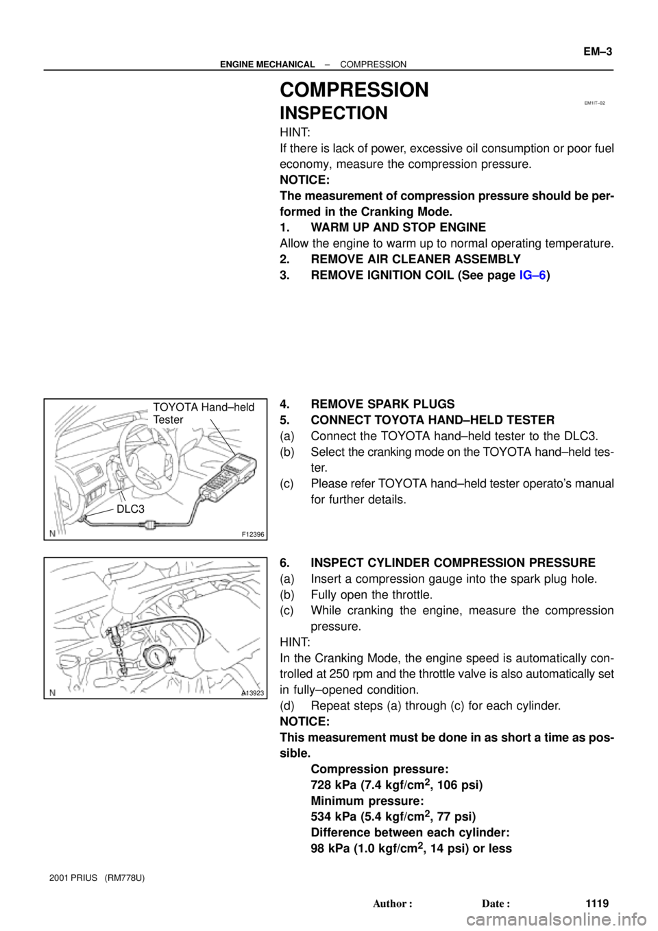
5. CONNECT TOYOTA HAND±HELD TESTER
(a) Connect the TOYOTA hand±held tester to the DLC3.
(b) Select the cranking mode on the TOYOTA hand±held tes-
ter.
(c) Please refer TOYOTA hand±held tester operato's manual
for further details.
6. INSPECT CYLINDER COMPRESSION PRESSURE
(a) Insert a compression gauge into the spark plug hole.
(b) Fully open the throttle.
(c) While cranking the engine, measure the compression
pressure.
HINT:
In the Cranking Mode, the engine speed is automatically con-
trolled at 250 rpm and the throttle valve is also automatically set
in fully±opened condition.
(d) Repeat steps (a) through (c) for each cylinder.
NOTICE:
This measurement must be done in as short a time as pos-
sible.
Compression pressure:
728 kPa (7.4 kgf/cm
2, 106 psi)
Minimum pressure:
534 kPa (5.4 kgf/cm
2, 77 psi)
Difference between each cylinder:
98 kPa (1.0 kgf/cm
2, 14 psi) or less
Page 1573 of 1943
± COOLINGCOOLANT
CO±3
2001 PRIUS (RM778U)
(f) Remove the radiator cap and check the engine coolant
level of the radiator. If it has dropped, repeat steps (d) to
(g).
(g) Bleed air from water pump.
Set the vehicle in the following conditions:
�Ignition switch ON
�Blower speed control dial to LO
�Temperature control dial to MAX. HOT
(h) Operate the water pump in the following conditions:
�The engine stopped
�The blower switch ON
�Temperature control dial at MAX. HOT
HINT:
Operate the water pump until a sound of the air±containing en-
gine coolant can not be heard from the heater core.
(i) When the engine coolant remains full, fill the radiator res-
ervoir tank with engine coolant to the maximum level.
3. CHECK FOR COOLANT LEAKS
4. CHECK ENGINE COOLANT SPECIFIC GRAVITY IS
CORRECT
Page 1722 of 1943
H15218
H15513
H15517
H15675
± SUPPLEMENTAL RESTRAINT SYSTEMSRS AIRBAG
RS±3
2001 PRIUS (RM778U)
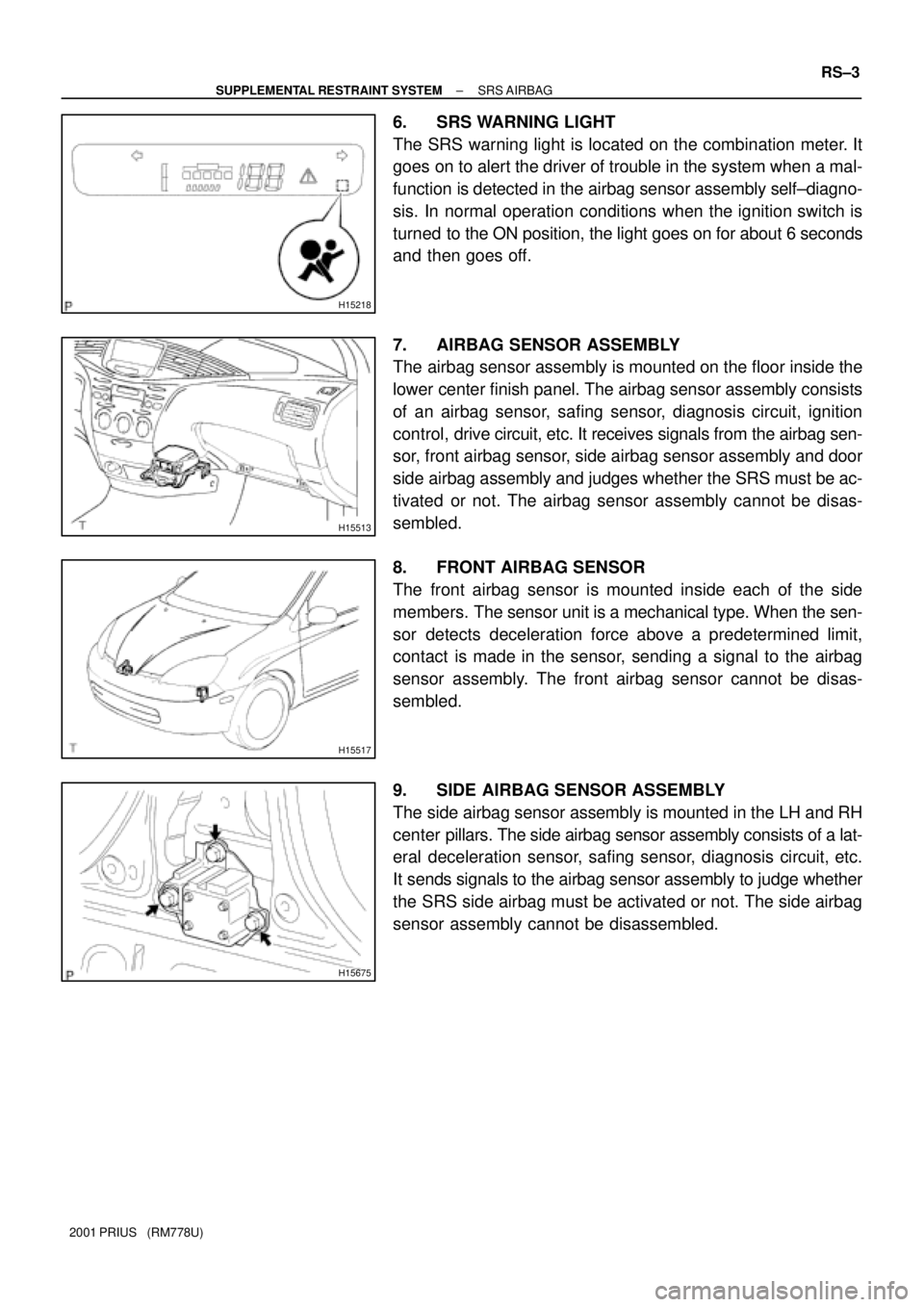
6. SRS WARNING LIGHT
The SRS warning light is located on the combination meter. It
goes on to alert the driver of trouble in the system when a mal-
function is detected in the airbag sensor assembly self±diagno-
sis. In normal operation conditions when the ignition switch is
turned to the ON position, the light goes on for about 6 seconds
and then goes off.
7. AIRBAG SENSOR ASSEMBLY
The airbag sensor assembly is mounted on the floor inside the
lower center finish panel. The airbag sensor assembly consists
of an airbag sensor, safing sensor, diagnosis circuit, ignition
control, drive circuit, etc. It receives signals from the airbag sen-
sor, front airbag sensor, side airbag sensor assembly and door
side airbag assembly and judges whether the SRS must be ac-
tivated or not. The airbag sensor assembly cannot be disas-
sembled.
8. FRONT AIRBAG SENSOR
The front airbag sensor is mounted inside each of the side
members. The sensor unit is a mechanical type. When the sen-
sor detects deceleration force above a predetermined limit,
contact is made in the sensor, sending a signal to the airbag
sensor assembly. The front airbag sensor cannot be disas-
sembled.
9. SIDE AIRBAG SENSOR ASSEMBLY
The side airbag sensor assembly is mounted in the LH and RH
center pillars. The side airbag sensor assembly consists of a lat-
eral deceleration sensor, safing sensor, diagnosis circuit, etc.
It sends signals to the airbag sensor assembly to judge whether
the SRS side airbag must be activated or not. The side airbag
sensor assembly cannot be disassembled.
Page 1787 of 1943
BE1VU±02
I17803
Connector ºAº Connector ºBº BE±42
± BODY ELECTRICALCOMBINATION METER
2001 PRIUS (RM778U)
INSPECTION
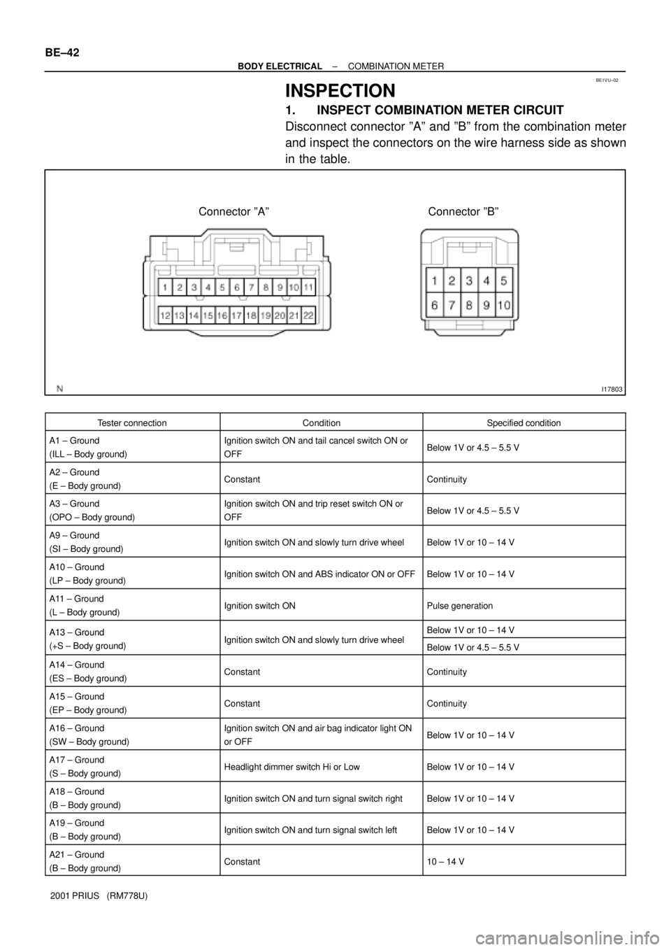
1. INSPECT COMBINATION METER CIRCUIT
Disconnect connector ºAº and ºBº from the combination meter
and inspect the connectors on the wire harness side as shown
in the table.
Tester connectionConditionSpecified condition
A1 ± Ground
(ILL ± Body ground)Ignition switch ON and tail cancel switch ON or
OFFBelow 1V or 4.5 ± 5.5 V
A2 ± Ground
(E ± Body ground)ConstantContinuity
A3 ± Ground
(OPO ± Body ground)Ignition switch ON and trip reset switch ON or
OFFBelow 1V or 4.5 ± 5.5 V
A9 ± Ground
(SI ± Body ground)Ignition switch ON and slowly turn drive wheelBelow 1V or 10 ± 14 V
A10 ± Ground
(LP ± Body ground)Ignition switch ON and ABS indicator ON or OFFBelow 1V or 10 ± 14 V
A11 ± Ground
(L ± Body ground)Ignition switch ONPulse generation
A13 ± GroundI iti it h ON d l l t d i h lBelow 1V or 10 ± 14 VA13 Ground
(+S ± Body ground)Ignition switch ON and slowly turn drive wheelBelow 1V or 4.5 ± 5.5 V
A14 ± Ground
(ES ± Body ground)ConstantContinuity
A15 ± Ground
(EP ± Body ground)ConstantContinuity
A16 ± Ground
(SW ± Body ground)Ignition switch ON and air bag indicator light ON
or OFFBelow 1V or 10 ± 14 V
A17 ± Ground
(S ± Body ground)Headlight dimmer switch Hi or LowBelow 1V or 10 ± 14 V
A18 ± Ground
(B ± Body ground)Ignition switch ON and turn signal switch rightBelow 1V or 10 ± 14 V
A19 ± Ground
(B ± Body ground)Ignition switch ON and turn signal switch leftBelow 1V or 10 ± 14 V
A21 ± Ground
(B ± Body ground)Constant10 ± 14 V
Page 1906 of 1943
AC2810
AC0Y9±05
AC2811
N11084
Wrong Okay
HI LO HILO
± AIR CONDITIONINGAIR CONDITIONING SYSTEM
AC±1
1889 Author�: Date�:
2001 PRIUS (RM778U)
AIR CONDITIONING SYSTEM
PRECAUTION
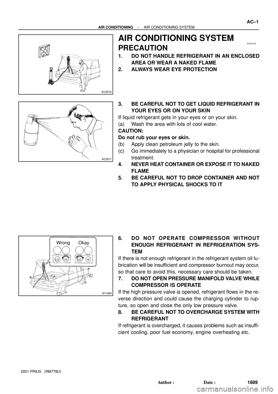
1. DO NOT HANDLE REFRIGERANT IN AN ENCLOSED
AREA OR WEAR A NAKED FLAME
2. ALWAYS WEAR EYE PROTECTION
3. BE CAREFUL NOT TO GET LIQUID REFRIGERANT IN
YOUR EYES OR ON YOUR SKIN
If liquid refrigerant gets in your eyes or on your skin.
(a) Wash the area with lots of cool water.
CAUTION:
Do not rub your eyes or skin.
(b) Apply clean petroleum jelly to the skin.
(c) Go immediately to a physician or hospital for professional
treatment.
4. NEVER HEAT CONTAINER OR EXPOSE IT TO NAKED
FLAME
5. BE CAREFUL NOT TO DROP CONTAINER AND NOT
TO APPLY PHYSICAL SHOCKS TO IT
6. DO NOT OPERATE COMPRESSOR WITHOUT
ENOUGH REFRIGERANT IN REFRIGERATION SYS-
TEM
If there is not enough refrigerant in the refrigerant system oil lu-
brication will be insufficient and compressor burnout may occur,
so that care to avoid this, necessary care should be taken.
7. DO NOT OPEN PRESSURE MANIFOLD VALVE WHILE
COMPRESSOR IS OPERATE
If the high pressure valve is opened, refrigerant flows in the re-
verse direction and could cause the charging cylinder to rup-
ture, so open and close the only low pressure valve.
8. BE CAREFUL NOT TO OVERCHARGE SYSTEM WITH
REFRIGERANT
If refrigerant is overcharged, it causes problems such as insuffi-
cient cooling, poor fuel economy, engine overheating etc.
Page 1907 of 1943
AC±2
± AIR CONDITIONINGAIR CONDITIONING SYSTEM
1890 Author�: Date�:
2001 PRIUS (RM778U)
9. SUPPLEMENTAL RESTRAINT SYSTEM (SRS)
The PRIUS is equipped with an SRS (Supplemental Restraint
System) such as the driver, front passenger and side airbag.
Failure to carry out service operation in the correct sequence
could cause the SRS to unexpectedly deploy during servicing,
possibly leading to a serious accident. Before servicing ( includ-
ing removal or installation of parts, inspection or replacement),
be sure to read the precautionary notices in the RS section.
Page 1908 of 1943
AC0YB±04
I17971
ight Glass
± AIR CONDITIONINGAIR CONDITIONING SYSTEM
AC±3
2001 PRIUS (RM778U)
ON±VEHICLE INSPECTION
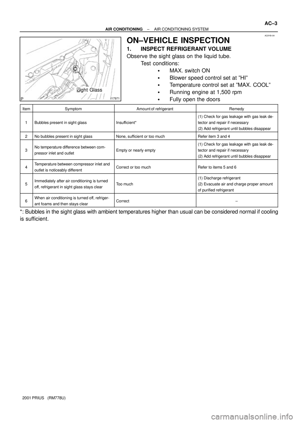
1. INSPECT REFRIGERANT VOLUME
Observe the sight glass on the liquid tube.
Test conditions:
�MAX. switch ON
�Blower speed control set at ºHIº
�Temperature control set at ºMAX. COOLº
�Running engine at 1,500 rpm
�Fully open the doors
ItemSymptomAmount of refrigerantRemedy
1Bubbles present in sight glassInsufficient*
(1) Check for gas leakage with gas leak de-
tector and repair if necessary
(2) Add refrigerant until bubbles disappear
2No bubbles present in sight glassNone, sufficient or too muchRefer item 3 and 4
3No temperature difference between com-
pressor inlet and outletEmpty or nearly empty
(1) Check for gas leakage with gas leak de-
tector and repair if necessary
(2) Add refrigerant until bubbles disappear
4Temperature between compressor inlet and
outlet is noticeably differentCorrect or too muchRefer to items 5 and 6
5Immediately after air conditioning is turned
off, refrigerant in sight glass stays clearToo much
(1) Discharge refrigerant
(2) Evacuate air and charge proper amount
of purified refrigerant
6When air conditioning is turned off, refriger-
ant foams and then stays clearCorrect±
*: Bubbles in the sight glass with ambient temperatures higher than usual can be considered normal if cooling
is sufficient.
Page 1909 of 1943
I01386
AC±4
± AIR CONDITIONINGAIR CONDITIONING SYSTEM
2001 PRIUS (RM778U)
2. INSPECT REFRIGERANT PRESSURE WITH MAN-
IFOLD GAUGE SET
This is a method in which the trouble is located by using a man-
ifold gauge set. Read the manifold gauge pressure when the
these conditions are established.
Test conditions:
�Temperature at the air inlet with the switch set
at RECIRC is 30 ± 35 °C (86 ± 95 °F)
�Engine running at 1500 rpm
�Blower speed control switch at ºHIº position
�Temperature control dial on ºCOOLº position
HINT:
It should be noted that the gauge indications may vary slightly
due to ambient temperature conditions.
(1) Normally functioning refrigeration system.
Gauge reading:
Low pressure side:
0.15 ± 0.25 MPa (1.5 ± 2.5 kgf/cm
2)
High pressure side:
1.37 ± 1.57 MPa (14 ± 16 kgf/cm
2)