Page 333 of 1943

THS (TOYOTA HYBRID SYSTEM)
182TH26
Inverter
Converter
182TH15
Inverter
HV
Battery
Ignition Signal
Ground
Voltage
Detection
Circuit
Voltage
Detection
Circuit
Bridge Circuit for MG2
Amperage
Sensor
Signal Processor /
Protective Function Processor
Bridge Circuit for MG1
Amperage
Sensor
MG2
HV ECU
MG1
182TH27
Reservoir Tank
Radiator
Water Pump35
INVERTER
1. General
The inverter is an electric power converter that
converts the direct current of the Hybrid vehicle's
high-voltage battery (DC 273.6 V) and the alter-
nating current of the MG1 and MG2.
Consisting of 2 three-phase bridge circuits for
MG1 and MG2, respectively, and each containing
6 power transistors, the inverter converts direct
current and three-phase alternating current. The ac-
tivation of the power transistors is controlled by the
HV ECU. In addition, the inverter transmits in-
formation that is needed for current control, such as
the output amperage or voltage, to the HV ECU.
Together with MG1 and MG2, the inverter is
cooled by the dedicated radiator of the coolant
system that is separate from that of the engine.
2. System Diagram
3. Cooling System
A cooling system via water pump for the inverter
and MG1, 2 has been added.
The HV ECU controls the water pump with cool-
ant temperature.
It is separated with the engine cooling system.
Page 510 of 1943

MA02G±02
MA±4
± MAINTENANCEUNDER HOOD
57 Author�: Date�:
2001 PRIUS (RM778U)
UNDER HOOD
GENERAL MAINTENANCE
1. GENERAL NOTES
�Maintenance items may vary from country to country. Check the owner's manual supplement in which
the maintenance schedule is shown.
�Every serice item in the periodic maintenance schedule must be performed.
�Periodic maintenance service must be performed according to whichever interval in the periodic main-
tenance schedule occurs first, the odometer reading (miles) or the time interval (months).
�Maintenance service after the last period should be performed at the same interval as before unless
otherwise noted.
2. WINDSHIELD WASHER FLUID
Check that there is sufficient fluid in the tank.
3. ENGINE COOLANT LEVEL
Check that the coolant level is between the ºFULLº and ºLOWº lines on the see±through reservoir.
4. RADIATOR AND HOSES
(a) Check that the front of the radiator is clean and not blocked with leaves, dirt or bugs.
(b) Check the hoses for cracks, kinks, rot or loose connections.
5. BRAKE FLUID LEVELS
Check that the brake fluid levels are near the upper level line on the see±through reservoirs.
6. CHECK TRANSAXLE OIL (FLUID)
�Visually check the transaxle for oil (fluid) leakage.
�If leakage is found, check for the cause and repair.
HINT:
Wait until the engine and motor cools down (approx. 30 min.) before checking the fluid level after extended
driving at high speeds, in hot weather, in heavy traffic or pulling a trailer.
Page 1474 of 1943
EM173±04
A13942
Hood to Cowl Top
seal
VSV for EVAPR/B (ABS) Air Cleaner
Assembly
RH Engine Mounting
Insulator Engine Coolant
Reservoir Tank
Engine Under
Cover RH
N´m (kgf´cm, ft´lbf) : Specified torqueOuter Front Cowl
Top Panel Air Inlet
60 (612, 44)
52 (530, 38)
52 (530, 38)
26 (265, 19)Brake Reservoir
Tank
Wiper Motor and
Wiper Link
Assembly
Cowl Top Ventilator
Lower LH
Cowl Top Ventilator
Lower RH
Wiper Arm
7 (71, 62 in. lbf)
26 (265, 19)
± ENGINE MECHANICALTIMING CHAIN
EM±13
1129 Author�: Date�:
2001 PRIUS (RM778U)
TIMING CHAIN
COMPONENTS
Page 1476 of 1943

EM1IU±03
A13907
A13908
A13934
A13943
± ENGINE MECHANICALTIMING CHAIN
EM±15
2001 PRIUS (RM778U)
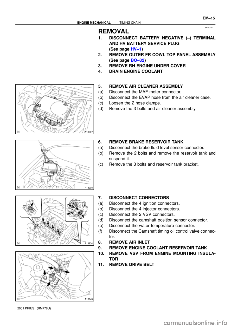
REMOVAL
1. DISCONNECT BATTERY NEGATIVE (±) TERMINAL
AND HV BATTERY SERVICE PLUG
(See page HV±1)
2. REMOVE OUTER FR COWL TOP PANEL ASSEMBLY
(See page BO±32)
3. REMOVE RH ENGINE UNDER COVER
4. DRAIN ENGINE COOLANT
5. REMOVE AIR CLEANER ASSEMBLY
(a) Disconnect the MAF meter connector.
(b) Disconnect the EVAP hose from the air cleaner case.
(c) Loosen the 2 hose clamps.
(d) Remove the 3 bolts and air cleaner assembly.
6. REMOVE BRAKE RESERVOIR TANK
(a) Disconnect the brake fluid level sensor connector.
(b) Remove the 2 bolts and remove the reservoir tank and
suspend it.
(c) Remove the 3 bolts and reservoir tank bracket.
7. DISCONNECT CONNECTORS
(a) Disconnect the 4 ignition connectors.
(b) Disconnect the 4 injector connectors.
(c) Disconnect the 2 VSV connectors.
(d) Disconnect the camshaft position sensor connector.
(e) Disconnect the water temperature connector.
(f) Disconnect the Camshaft timing oil control valve connec-
tor.
8. REMOVE AIR INLET
9. REMOVE ENGINE COOLANT RESERVOIR TANK
10. REMOVE VSV FROM ENGINE MOUNTING INSULA-
TOR
11. REMOVE DRIVE BELT
Page 1483 of 1943

A11262
SST
SST
B00301
Seal
Packing
A11222
1
23
4
5
6
7
8
9
10
11
B11761
A13928
EM±24
± ENGINE MECHANICALTIMING CHAIN
2001 PRIUS (RM778U)
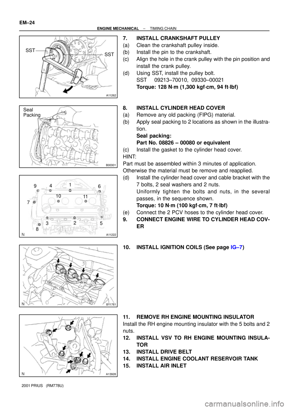
7. INSTALL CRANKSHAFT PULLEY
(a) Clean the crankshaft pulley inside.
(b) Install the pin to the crankshaft.
(c) Align the hole in the crank pulley with the pin position and
install the crank pulley.
(d) Using SST, install the pulley bolt.
SST 09213±70010, 09330±00021
Torque: 128 N´m (1,300 kgf´cm, 94 ft´lbf)
8. INSTALL CYLINDER HEAD COVER
(a) Remove any old packing (FIPG) material.
(b) Apply seal packing to 2 locations as shown in the illustra-
tion.
Seal packing:
Part No. 08826 ± 00080 or equivalent
(c) Install the gasket to the cylinder head cover.
HINT:
Part must be assembled within 3 minutes of application.
Otherwise the material must be remove and reapplied.
(d) Install the cylinder head cover and cable bracket with the
7 bolts, 2 seal washers and 2 nuts.
Uniformly tighten the bolts and nuts, in the several
passes, in the sequence shown.
Torque: 10 N´m (100 kgf´cm, 7 ft´lbf)
(e) Connect the 2 PCV hoses to the cylinder head cover.
9. CONNECT ENGINE WIRE TO CYLINDER HEAD COV-
ER
10. INSTALL IGNITION COILS (See page IG±7)
11. REMOVE RH ENGINE MOUNTING INSULATOR
Install the RH engine mounting insulator with the 5 bolts and 2
nuts.
12. INSTALL VSV TO RH ENGINE MOUNTING INSULA-
TOR
13. INSTALL DRIVE BELT
14. INSTALL ENGINE COOLANT RESERVOIR TANK
15. INSTALL AIR INLET
Page 1484 of 1943
A13934
A13907
± ENGINE MECHANICALTIMING CHAIN
EM±25
2001 PRIUS (RM778U)
16. CONNECT CONNECTORS
(a) Connect the Camshaft timing oil control valve connector.
(b) Connect the water temperature sensor connector.
(c) Connect the camshaft position sensor connector.
(d) Connect the 2 VSV connectors.
(e) Connect the 4 injector connectors.
(f) Connect the 4 ignition connectors.
17. INSTALL AIR CLEANER ASSEMBLY
(a) Install the air cleaner assembly with the 2 bolts.
(b) Tighten the 2 hose clamps.
(c) Connect the EVAP hose to the air cleaner case.
(d) Connect the MAF meter connector.
18. INSTALL BRAKE RESERVOIR TANK
19. INSTALL OUTER FR COWL TOP PANEL ASSEMBLY
(See page BO±35)
20. FILL WITH ENGINE COOLANT
21. INSTALL ENGINE UNDER COVERS
22. CONNECT BATTERY NEGATIVE (±) TERMINAL AND
HV BATTERY SERVICE PLUG (See page HV±1)
23. ROAD TEST VEHICLE
Check for abnormal noises, shock slippage, correst shift points
and smooth operation.
24. RECHECK ENGINE COOLANT AND HV TRANSAXLE
COOLANT
Page 1485 of 1943
EM1IW±02
A13929
N´m (kgf´cm, ft´lbf)� Gasket
: Specified torque VSV for EVAPR/B (ABS) Air Cleaner
Assembly
RH Engine Mounting
Insulator Engine Coolant
Reservoir Tank
Engine Under
Cover RHOuter Front Cowl
Top Panel Air Inlet
60 (612, 44)
52 (530, 38)
52 (530, 38)
26 (265, 19)Brake Reservoir
Tank
Wiper Motor and
Wiper Link
Assembly
Cowl Top Ventilator
Lower LH
Cowl Top Ventilator
Lower RH
Wiper Arm
7 (71, 62 in. lbf)
26 (265, 19)
Hood to Cowl Top
Seal
62 (630, 46)
Front Exhaust Pipe
EM±26
± ENGINE MECHANICALCYLINDER HEAD
1142 Author�: Date�:
2001 PRIUS (RM778U)
CYLINDER HEAD
COMPONENTS
Page 1508 of 1943
EM1IZ±02
A13904
Front BumperR/B (ABS)
Air Cleaner
Assembly Engine Coolant
Reservoir Tank
Engine Under
CoverOuter Front Cowl
Top Panel Air Inlet
Brake Reservoir
Tank
Wiper Motor and
Wiper Link
Assembly
Cowl Top Ventilator
Lower LH
Cowl Top Ventilator
Lower RH
Wiper Arm
Hood to Cowl Top
Seal
N´m (kgf´cm, ft´lbf) : Specified torque
26 (265, 19)
7 (71, 62 in. lbf)
26 (265, 19)
11.5 (117, 8)
Head Light RH
EM±50
± ENGINE MECHANICALENGINE UNIT
1166 Author�: Date�:
2001 PRIUS (RM778U)
ENGINE UNIT
COMPONENTS