Page 1511 of 1943
EM1J0±02
A13907
A13943
± ENGINE MECHANICALENGINE UNIT
EM±53
2001 PRIUS (RM778U)
REMOVAL
1. DISCONNECT BATTERY NEGATIVE (±) TERMINAL
AND HV BATTERY SERVICE PLUG
(See page HV±1)
2. REMOVE OUTER FRONT COWL TOP PANEL AS-
SEMBLY (See page BO±32)
3. DRAIN HV COOLANT (See page HT±8)
4. DRAIN ENGINE COOLANT
5. REMOVE CONVERTER AND INVERTER ASSEMBLY
(See page HV±18)
6. REMOVE HEATER UNIT WATER PUMP
(See page AC±55)
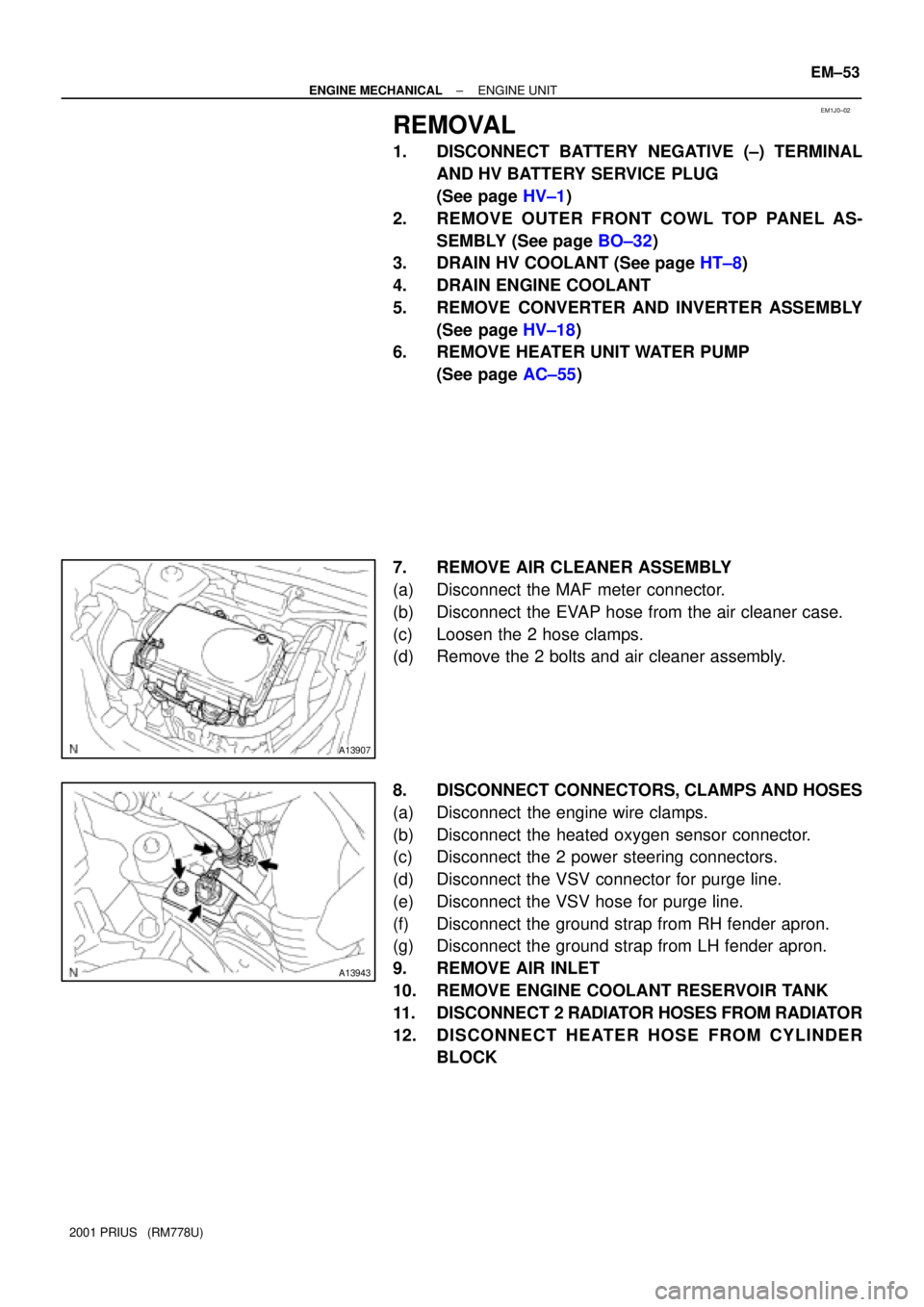
7. REMOVE AIR CLEANER ASSEMBLY
(a) Disconnect the MAF meter connector.
(b) Disconnect the EVAP hose from the air cleaner case.
(c) Loosen the 2 hose clamps.
(d) Remove the 2 bolts and air cleaner assembly.
8. DISCONNECT CONNECTORS, CLAMPS AND HOSES
(a) Disconnect the engine wire clamps.
(b) Disconnect the heated oxygen sensor connector.
(c) Disconnect the 2 power steering connectors.
(d) Disconnect the VSV connector for purge line.
(e) Disconnect the VSV hose for purge line.
(f) Disconnect the ground strap from RH fender apron.
(g) Disconnect the ground strap from LH fender apron.
9. REMOVE AIR INLET
10. REMOVE ENGINE COOLANT RESERVOIR TANK
11. DISCONNECT 2 RADIATOR HOSES FROM RADIATOR
12. DISCONNECT HEATER HOSE FROM CYLINDER
BLOCK
Page 1517 of 1943
A13939
I18009
A13909
A13938
EM±60
± ENGINE MECHANICALENGINE UNIT
2001 PRIUS (RM778U)
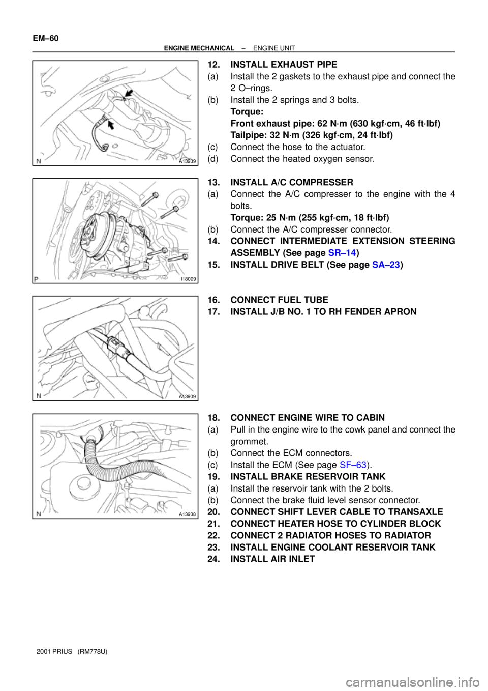
12. INSTALL EXHAUST PIPE
(a) Install the 2 gaskets to the exhaust pipe and connect the
2 O±rings.
(b) Install the 2 springs and 3 bolts.
Torque:
Front exhaust pipe: 62 N´m (630 kgf´cm, 46 ft´lbf)
Tailpipe: 32 N´m (326 kgf´cm, 24 ft´lbf)
(c) Connect the hose to the actuator.
(d) Connect the heated oxygen sensor.
13. INSTALL A/C COMPRESSER
(a) Connect the A/C compresser to the engine with the 4
bolts.
Torque: 25 N´m (255 kgf´cm, 18 ft´lbf)
(b) Connect the A/C compresser connector.
14. CONNECT INTERMEDIATE EXTENSION STEERING
ASSEMBLY (See page SR±14)
15. INSTALL DRIVE BELT (See page SA±23)
16. CONNECT FUEL TUBE
17. INSTALL J/B NO. 1 TO RH FENDER APRON
18. CONNECT ENGINE WIRE TO CABIN
(a) Pull in the engine wire to the cowk panel and connect the
grommet.
(b) Connect the ECM connectors.
(c) Install the ECM (See page SF±63).
19. INSTALL BRAKE RESERVOIR TANK
(a) Install the reservoir tank with the 2 bolts.
(b) Connect the brake fluid level sensor connector.
20. CONNECT SHIFT LEVER CABLE TO TRANSAXLE
21. CONNECT HEATER HOSE TO CYLINDER BLOCK
22. CONNECT 2 RADIATOR HOSES TO RADIATOR
23. INSTALL ENGINE COOLANT RESERVOIR TANK
24. INSTALL AIR INLET
Page 1576 of 1943
CO145±01
I17955
I17954
± COOLINGRADIATOR AND CONDENSER MODULE
CO±17
2001 PRIUS (RM778U)
REMOVAL
1. DISCHARGE REFRIGERANT FROM REFRIGERATION
SYSTEM
HINT:
At the time of installation, please refer to the following item.
Evacuate air from refrigeration system.
Charge system with refrigerant and inspect for leakage of refrig-
erant.
Specified amount: 500 ± 50 g (17.64 ± 1.76 oz.)
2. DRAIN ENGINE COOLANT FROM RADIATOR
HINT:
It is not necessary to drain out all the coolant.
3. REMOVE ELECTRIC COOLING FAN ASSEMBLY
(See Page CO±22)
4. REMOVE FRONT BUMPER (See Page BO±4)
5. REMOVE RADIATOR RESERVOIR HOSE
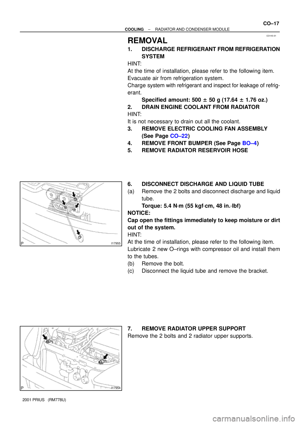
6. DISCONNECT DISCHARGE AND LIQUID TUBE
(a) Remove the 2 bolts and disconnect discharge and liquid
tube.
Torque: 5.4 N´m (55 kgf´cm, 48 in.´lbf)
NOTICE:
Cap open the fittings immediately to keep moisture or dirt
out of the system.
HINT:
At the time of installation, please refer to the following item.
Lubricate 2 new O±rings with compressor oil and install them
to the tubes.
(b) Remove the bolt.
(c) Disconnect the liquid tube and remove the bracket.
7. REMOVE RADIATOR UPPER SUPPORT
Remove the 2 bolts and 2 radiator upper supports.
Page 1584 of 1943
LU02M±08
A13942
Wiper Arm
VSV for EVAPAir Cleaner
Assembly
RH Engine Mounting
Insulator
Engine Under
Cover RH
N´m (kgf´cm, ft´lbf) : Specified torqueOuter Front Cowl
Top Panel
26 (265, 19)
52 (530, 38)
60 (612, 44)
52 (530, 38)
Air Inlet
Engine Coolant
Reservoir TankBrake reservoir
Tank
Wiper Motor and
Wiper Link
AssemblyHeat to Cowl Top
Seal
Cowl Top Ventilator
Lower LH Cowl Top Ventilator
Lower LH
R/B (ABS)
26 (265, 19)
7 (71, 62 in. lbf)
LU±4
± LUBRICATIONOIL PUMP
1310 Author�: Date�:
2001 PRIUS (RM778U)
OIL PUMP
COMPONENTS
Page 1611 of 1943
D09920Drain Plug
D09925
Oil Level
0 ± 5 mm
HT005±01
D09921Drain Plug
D09778
Shop Rag
D09899
HT±6
± HYBRID TRANSAXLEHYBRID TRANSAXLE UNIT
1379 Author�: Date�:
2001 PRIUS (RM778U)
HYBRID TRANSAXLE UNIT
ON±VEHICLE REPAIR
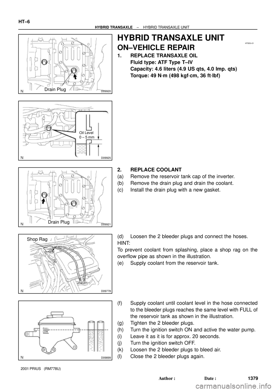
1. REPLACE TRANSAXLE OIL
Fluid type: ATF Type T±IV
Capacity: 4.6 liters (4.9 US qts, 4.0 Imp. qts)
Torque: 49 N´m (498 kgf´cm, 36 ft´lbf)
2. REPLACE COOLANT
(a) Remove the reservoir tank cap of the inverter.
(b) Remove the drain plug and drain the coolant.
(c) Install the drain plug with a new gasket.
(d) Loosen the 2 bleeder plugs and connect the hoses.
HINT:
To prevent coolant from splashing, place a shop rag on the
overflow pipe as shown in the illustration.
(e) Supply coolant from the reservoir tank.
(f) Supply coolant until coolant level in the hose connected
to the bleeder plugs reaches the same level with FULL of
the reservoir tank as shown in the illustration.
(g) Tighten the 2 bleeder plugs.
(h) Turn the ignition switch ON and active the water pump.
(i) Leave it as it is for approx. 20 seconds.
(j) Turn the ignition switch OFF.
(k) Loosen the 2 bleeder plugs to bleed air.
(l) Close the 2 bleeder plugs again.
Page 1612 of 1943
D09898
Coolant Level
± HYBRID TRANSAXLEHYBRID TRANSAXLE UNIT
HT±7
1380 Author�: Date�:
2001 PRIUS (RM778U)
(m) Report the step (h) to (l) until the operation sound of the
pump becomes lower and Coolant in the reservoir tank
moves faster.
(n) With the ignition switch ON, wait for applox. 5 minutes.
(o) Adjust the coolant level inside the reservoir tank as shown
in the illustration.
Page 1926 of 1943
AC36R±01
I17955
I17954
± AIR CONDITIONINGRADIATOR AND CONDENSER MODULE
AC±47
2001 PRIUS (RM778U)
REMOVAL
1. DISCHARGE REFRIGERANT FROM REFRIGERATION
SYSTEM
HINT:
At the time of installation, please refer to the following item.
Evacuate air from refrigeration system.
Charge system with refrigerant and inspect for leakage of refrig-
erant.
Specified amount: 500 ± 50 g (17.64 ± 1.76 oz.)
2. DRAIN ENGINE COOLANT FROM RADIATOR
HINT:
It is not necessary to drain out all the coolant.
3. REMOVE CONDENSER FAN ASSEMBLY
(See Page AC±69)
4. REMOVE FRONT BUMPER (See Page BO±4)
5. REMOVE RADIATOR RESERVOIR HOSE
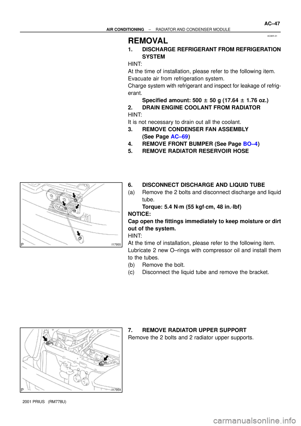
6. DISCONNECT DISCHARGE AND LIQUID TUBE
(a) Remove the 2 bolts and disconnect discharge and liquid
tube.
Torque: 5.4 N´m (55 kgf´cm, 48 in.´lbf)
NOTICE:
Cap open the fittings immediately to keep moisture or dirt
out of the system.
HINT:
At the time of installation, please refer to the following item.
Lubricate 2 new O±rings with compressor oil and install them
to the tubes.
(b) Remove the bolt.
(c) Disconnect the liquid tube and remove the bracket.
7. REMOVE RADIATOR UPPER SUPPORT
Remove the 2 bolts and 2 radiator upper supports.