Page 1035 of 1943

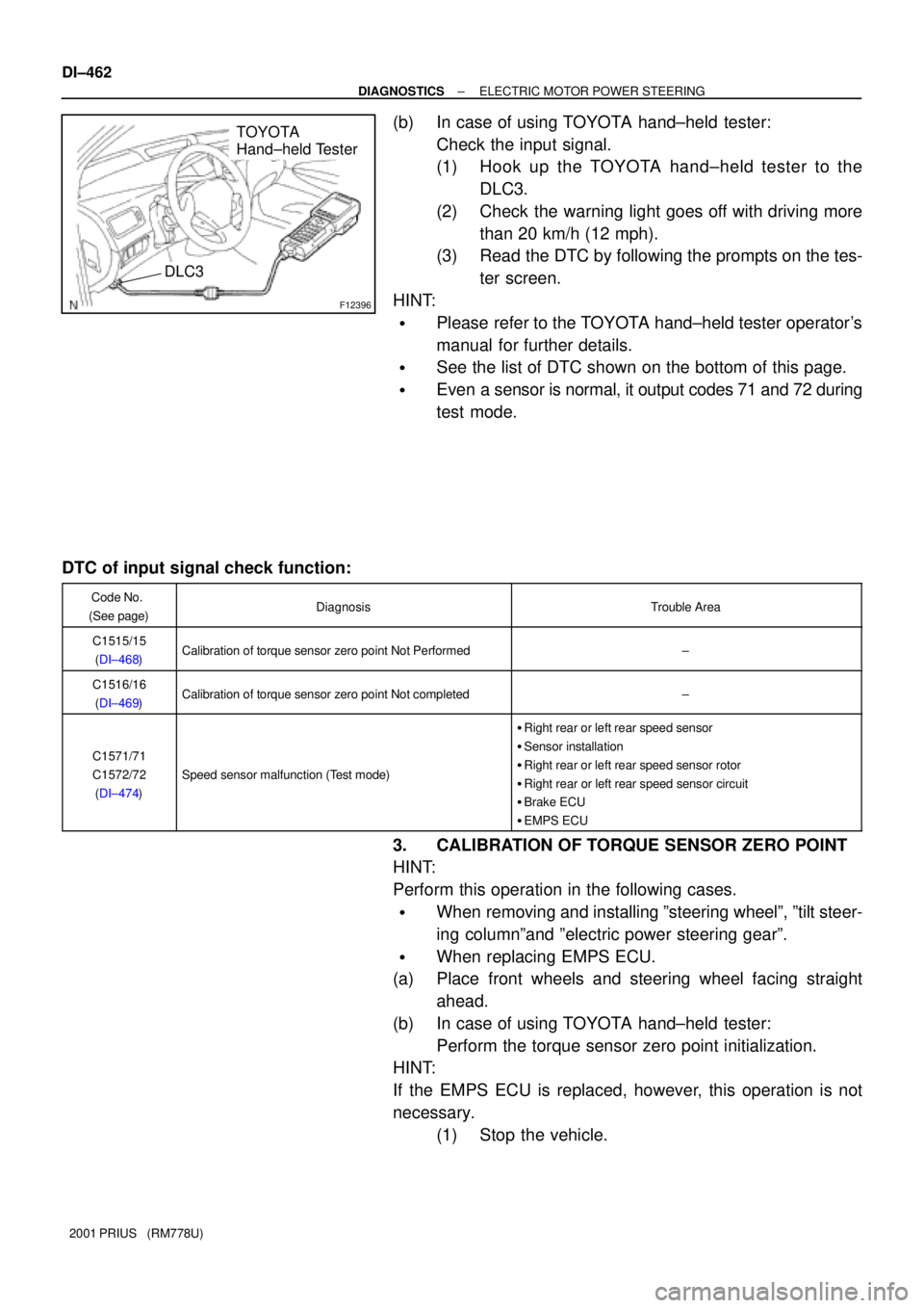
F12396
TOYOTA
Hand±held Tester
DLC3
DI±462
± DIAGNOSTICSELECTRIC MOTOR POWER STEERING
2001 PRIUS (RM778U)
(b) In case of using TOYOTA hand±held tester:
Check the input signal.
(1) Hook up the TOYOTA hand±held tester to the
DLC3.
(2) Check the warning light goes off with driving more
than 20 km/h (12 mph).
(3) Read the DTC by following the prompts on the tes-
ter screen.
HINT:
�Please refer to the TOYOTA hand±held tester operator's
manual for further details.
�See the list of DTC shown on the bottom of this page.
�Even a sensor is normal, it output codes 71 and 72 during
test mode.
DTC of input signal check function:
Code No.
(See page)DiagnosisTrouble Area
C1515/15
(DI±468)Calibration of torque sensor zero point Not Performed±
C1516/16
(DI±469)Calibration of torque sensor zero point Not completed±
C1571/71
C1572/72
(DI±474)
Speed sensor malfunction (Test mode)
�Right rear or left rear speed sensor
�Sensor installation
�Right rear or left rear speed sensor rotor
�Right rear or left rear speed sensor circuit
�Brake ECU
�EMPS ECU
3. CALIBRATION OF TORQUE SENSOR ZERO POINT
HINT:
Perform this operation in the following cases.
�When removing and installing ºsteering wheelº, ºtilt steer-
ing columnºand ºelectric power steering gearº.
�When replacing EMPS ECU.
(a) Place front wheels and steering wheel facing straight
ahead.
(b) In case of using TOYOTA hand±held tester:
Perform the torque sensor zero point initialization.
HINT:
If the EMPS ECU is replaced, however, this operation is not
necessary.
(1) Stop the vehicle.
Page 1038 of 1943

DI7QX±01
± DIAGNOSTICSELECTRIC MOTOR POWER STEERING
DI±465
2001 PRIUS (RM778U)
DIAGNOSTIC TROUBLE CODE CHART
HINT:
�Using SST 09843±18040, connect terminals Tc and CG of the DLC3.
�If a malfunction code is displayed during the DTC check, check the circuit listed for the code. For details
of each code, turn to the page referred to under the ºSee pageº for respective ºDTC No.º in the DTC
chart.
DTC No.
(See page)Detection ItemTrouble Area
C1511/11
(DI±465)
C1512/12
(DI±465)
T i it lf ti�Torque sensor
C1513/13
(DI±465)Torque sensor circuit malfunction�Torque sensor
�EMPS ECU
C1514/14
(DI±465)
C1521/21
(DI±471)
C1522/22
(DI±471)
Mt i it lf ti�Power steering gear assembly with motor
C1523/23
(DI±471)Motor circuit malfunction�Power steering gear assembly with motor
�EMPS ECU
C1524/24
(DI±471)
C1531/31
(DI±473)
C1532/32
(DI±473)EMPS ECU malfunctionEMPS ECU
C1533/33
(DI±473)
C1541/41
(DI±474)
C1542/42
(DI±474)Speed sensor malfunction
�Speed sensor
�Brake ECU
�EMPS ECUC1543/43
(DI±474)�EMPS ECU
C1551/51
(DI±476)IG power source circuit malfunction
�EMPS ECU
�Power source circuit
�Charging system
C1552/52
(DI±479)PIG power source drop voltage malfunction�EMPS ECU
�Power source circuit
C1553/53
(DI±482)When resetting voltage, vehicle is being drivenEMPS ECU
C1554/54
(DI±483)EMPS relay circuit malfunction
�EMPS relay
�EMPS ECU
�EMPS relay circuit
C1555/55
(DI±473)EMPS ECU malfunctionEMPS ECU
C1556/56
(DI±486)P/S warning light circuit�Multiinformation display
�EMPS ECU
Page 1039 of 1943
DI±466
± DIAGNOSTICSELECTRIC MOTOR POWER STEERING
2001 PRIUS (RM778U)C1557/57
(DI±488)
Memory of overheat prevention control±
C1558/58
(DI±488)Memory of voltage drop at motor power supply±
C1559/59
(DI±488)Memory of continuous control under high load±
Always ON
(DI±489)Malfunction in EMPS ECU
�Power source circuit
�EMPS ECU
�PS warning light circuit
Page 1058 of 1943
F12840
EMPS ECU
WL
E67
Y 3
IP1 L 11 Multiinformation Display
22
L
Instrument Panel J/B
IG1 Relay
3
51
2H GAUGE
2A5
W
FL Block No. 1
1
F11 F131
B±G
1 MAIN FL Block No. 2 F18
BatteryDC/DC
± DIAGNOSTICSELECTRIC MOTOR POWER STEERING
DI±491
2001 PRIUS (RM778U)
DTC C1556/56 P/S Warning Light Circuit
CIRCUIT DESCRIPTION
DTC No.DTC Detecting ConditionTrouble Area
C1556/56There is a malfunction in PS warning light circuit.�Multiinformation display
�EMPS ECU
WIRING DIAGRAM
DI7RB±01
Page 1060 of 1943
DI±494
± DIAGNOSTICSELECTRIC MOTOR POWER STEERING
2001 PRIUS (RM778U)
DTCAlways ONMalfunction in EMPS ECU
CIRCUIT DESCRIPTION
DTC No.DTC Detecting ConditionTrouble Area
Always ONThere is a malfunction in the EMPS ECU internal circuit.
�Power source circuit
�EMPS ECU
�PS warning light circuit
INSPECTION PROCEDURE
1 Is DTC output?
Check DTC on page DI±460.
YES Repair circuit indicated by output code.
NO
2 Is normal code displayed?
YES Check and replace EMPS ECU.
NO
3 Does PS warning light goes off?
YES Check for open or short circuit in harness and
connector between ECU±IG fuse and EMPS
ECU (See page IN±41).
NO
DI7RD±01
Page 1061 of 1943
± DIAGNOSTICSELECTRIC MOTOR POWER STEERING
DI±495
2001 PRIUS (RM778U)
4 Check battery positive voltage.
PREPARATION:
Start the engine.
CHECK:
Check the battery positive voltage.
OK:
Voltage: 9 ± 14 V
NG Check and repair charging system.
OK
5 Check operation of PS warning light.
PREPARATION:
(a) Turn the ignition switch OFF.
(b) Disconnect the connector from the EMPS ECU.
(c) Turn the ignition switch ON.
CHECK:
Check the PS warning light goes OFF.
OK Check and replace EMPS ECU.
NG
Check for short circuit in harness and connector between multiinformation display and EMPS
ECU, multiinformation display and DLC3 (See page IN±41).
Page 1062 of 1943
F12842
EMPS ECU
Tc
E63
P±B
C CJ16
J/C
P±B 2
ID1 P±B
E EJ26
J/C
P±B 13
Tc
5
SGBR14
ID2BR
BR 14
IO1
EB DLC3 DI±496
± DIAGNOSTICSELECTRIC MOTOR POWER STEERING
2001 PRIUS (RM778U)
Tc Terminal Circuit
CIRCUIT DESCRIPTION
Connecting terminals Tc and CG of the DLC3 causes the EMPS ECU to display the DTC by flashing the PS
warning light.
WIRING DIAGRAM
DI7RE±01
Page 1063 of 1943
F09678
ON
Tc
CG
± DIAGNOSTICSELECTRIC MOTOR POWER STEERING
DI±497
2001 PRIUS (RM778U)
INSPECTION PROCEDURE
1 Check voltage between terminals Tc and CG of DLC3.
CHECK:
Turn the ignition switch ON and measure the voltage between
terminals Tc and CG of the DLC3.
OK:
Voltage: 9 ± 14 V
OK If PS warning light does not blink even after Tc
and CG are connected, EMPS ECU may be de-
fective.
NG
2 Turn the ignition switch OFF, and check for open and short circuit in harness
and connector between EMPS ECU and DLC3, and DLC3 and body ground (See
page IN±41).
NG Repair or replace harness or connector.
OK
Check and replace EMPS ECU.